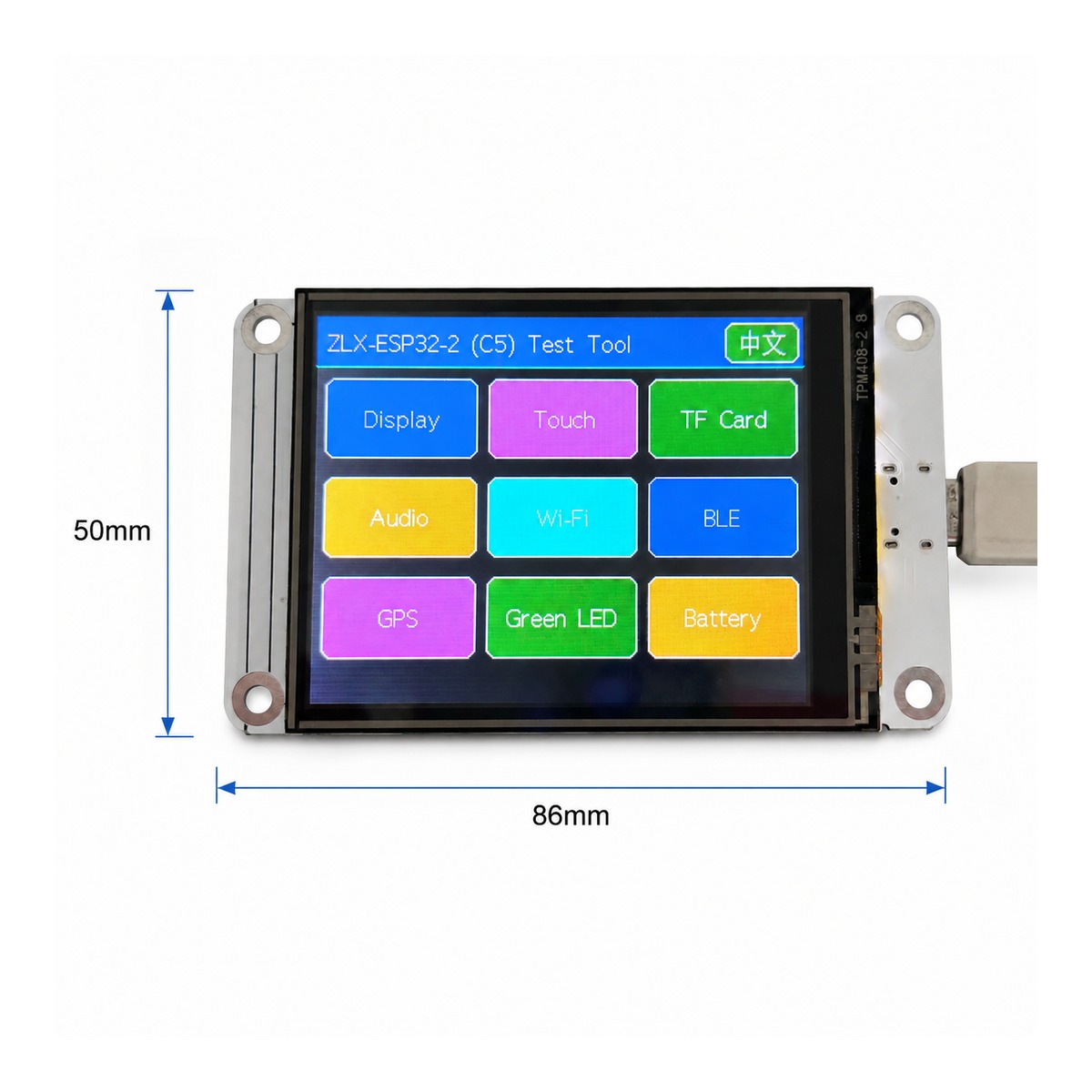
ZLX-ESP32-2
ESP32-C5 2.8-inch Touch Display Development Board
Gebruikershandleiding in het Chinees en Engels / Bilingual User Manual
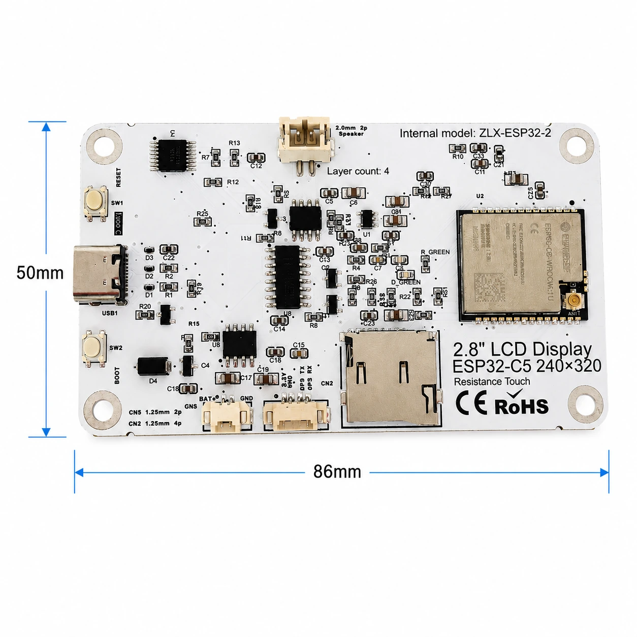
Model / Model: ZLX-ESP32-2
Module / Module: ESP32-C5-WROOM-1U-N8R8
Document Version / Documentversie: V1.1 | 2026-08-25
1. Productoverzicht / 1. Product Overview
ZLX-ESP32-2 is een model gebaseerd op ESP32-C5-WROOM-1U-N8R8 Module 2.8 Inch Resistive Touchscreen Development Board, Geïntegreerde kleur LCD、XPT2046 Raak aan,microSD/TF Kaartsleuf (alleen kaartsleuf, niet inbegrepen microSD/TF kaart),GPS Interface, audio-uitgang, accuspanningsdetectie, groen LED、BOOT/RESET Knop en externe antenne-interface. Geschikt voor Wi-Fi 6、Bluetooth LE、Zigbee/Thread, HMI, gegevensregistratie en IoT-applicatieontwikkeling.
ZLX-ESP32-2 is a 2.8-inch resistive-touch development board based on the ESP32-C5-WROOM-1U-N8R8 module. It integrates a color LCD, XPT2046 touch controller, a microSD/TF card slot (slot only; no microSD/TF card is included), GPS interface, audio output, battery-voltage sensing, green LED, BOOT/RESET buttons, and an external-antenna connector. It is suitable for Wi-Fi 6, Bluetooth LE, Zigbee/Thread, HMI, data logging, and IoT development.
Belangrijkste kenmerken / Key Features
ESP32-C5 32 bits RISC-V Eenkernprocessor, tot 240 MHz / ESP32-C5 32-bit RISC-V single-core CPU, up to 240 MHz
ESP32-C5-WROOM-1U-N8R8:8 MB Flash + 8 MB PSRAM(Module onboard resource, niet microSD/TF Kaart) / ESP32-C5-WROOM-1U-N8R8: 8 MB Flash + 8 MB PSRAM (onboard module memory, not a microSD/TF card)
2.4 GHz + 5 GHz Dual-band Wi-Fi 6(802.11ax) / 2.4 GHz + 5 GHz dual-band Wi-Fi 6 (802.11ax)
Bluetooth LE、IEEE 802.15.4、Zigbee 3.0、Thread 1.4 / Bluetooth LE, IEEE 802.15.4, Zigbee 3.0, Thread 1.4
2.8 Inch 240×320 LCD,ST7789 StuurprogrammaBGR Initialiseren, omgekeerde kleur niet inschakelen / 2.8-inch 240×320 LCD, ST7789 driver, BGR initialization, display inversion disabled
XPT2046 Resistieve aanraakcontroller / XPT2046 resistive touch controller
LCD En TF Kaart delen SPI Bus, zelfstandig CS; Aanraken met stand-alone software SPI / LCD and TF card share SPI with separate CS; touch uses an independent software SPI
Bordgrootte ca. 86 mm × 50 mm / Board size approx. 86 mm × 50 mm
IPEX1 Externe antenne-interface; sluit de externe antenne correct aan voordat u de draadloze functie gebruikt / IPEX1 external antenna connector; connect a suitable external antenna before radio use
Toepasselijke objecten / Intended Users
Geschikt voor embedded developers, IoT-ontwikkelaars, makers, onderwijsexperimenten en productprototyping.
For embedded developers, IoT developers, makers, education/lab use, and product prototyping.
2. Uiterlijk en afmetingen / 2. Appearance and Dimensions
De buitenafmetingen van de bordkaart zijn ongeveer 86 mm × 50 mm. De onderstaande voor- en achterfoto's worden gebruikt om het scherm, de interface en het hoofdapparaat te identificeren.
The board outline is approximately 86 mm × 50 mm. The images below help identify the display, connectors, and major components.
|
|
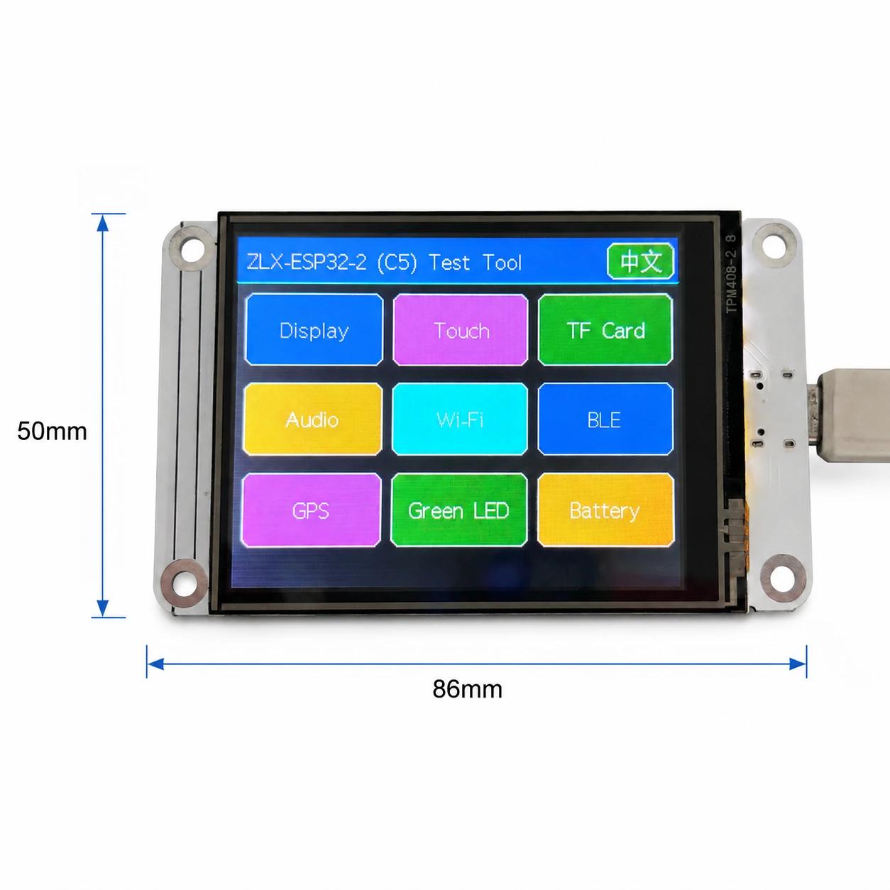
Fig. 1 Schema voor en schermgrootte / Figure 1 Board front and display-side dimensions
Interface-annotatie / Connector Identification
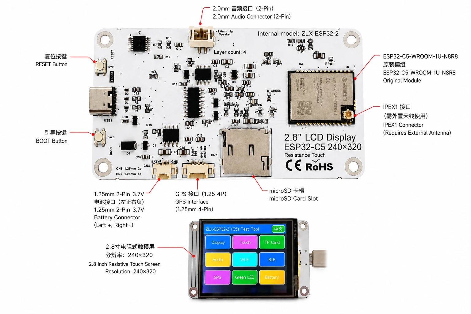
Fig. 2 ZLX-ESP32-2 Toelichting op de Chinees-Engelse interface / Figure 2 Bilingual connector identification
3. Specificaties ontwikkelbord / 3. Board Specifications
Project / Item | Specificaties / Specification |
Ontwikkelbordmodel / Board model | ZLX-ESP32-2 |
Kernmodules / Core module | ESP32-C5-WROOM-1U-N8R8 |
Bordgrootte / Board size | Approx. 86 × 50 mm |
Scherm / Display | 2.8-inch TFT LCD, ST7789, 240×320 native resolution |
Kleurvolgorde / Color order | BGR initialization |
Omgekeerde kleur weergeven / Display inversion | OFF / Normal display mode(Omgekeerde kleur wordt niet geopend) |
aanraken / Touch | Resistive touch / Resistieve aanraking, XPT2046 |
microSD/TF Kaartsleuf / microSD/TF Card Slot | SPI mode; card not included / SPI Modus; zonder kaart |
GPS Implementatie / GPS interface | 1.25 mm 4-pin connector; UART signals on GPIO0/GPIO9 |
Audio-interface / Audio | 2.0 mm 2-pin speaker/audio connector; PWM audio + amplifier enable |
Batterijconnector / Battery | 3.7 V 1S, 1.25 mm 2-pin; protected 1000–3000 mAh recommended / Enkele sectie 3.7 VSuggesties 1000–3000 mAh Met beschermplaat |
Externe antenne / External antenna | IPEX1 connector; required for the WROOM-1U radio path |
Knop / Buttons | RESET, BOOT |
Statusindicator / Indicator | Green LED on GPIO26 |
illustreren / Note: De native resolutie van het scherm is 240×320; Wanneer de software is ingesteld op liggende rotatie, kan de logische weergavegrootte worden weergegeven als 320×240。 / The panel native resolution is 240×320; in landscape rotation, the logical display size may be 320×240.
4. ESP32-C5-WROOM-1U-N8R8 Moduleparameters / 4. ESP32-C5-WROOM-1U-N8R8 Module Specifications
De volgende belangrijke parameters zijn gebaseerd op Espressif Officieel ESP32-C5-WROOM-1 / WROOM-1U Datasheet v1.2。
The following key parameters are based on Espressif's official ESP32-C5-WROOM-1 / WROOM-1U Datasheet v1.2.
Project / Item | Specificaties / Specification |
Ingebouwde chip / Embedded SoC | ESP32-C5HR8 |
CPU | 32-bit RISC-V single core, up to 240 MHz |
ROM | 320 KB |
HP SRAM | 384 KB |
LP SRAM | 16 KB |
Flash | 8 MB Quad SPI |
PSRAM | 8 MB Quad SPI |
Wi-Fi | 1T1R, 2.4 GHz + 5 GHz dual-band; IEEE 802.11ax/ac/b/g/n; up to 150 Mbps |
2.4 GHz Band / Frequency | 2412–2484 MHz |
5 GHz Band / Frequency | 5180–5885 MHz (subject to regional regulations) |
Bluetooth | Bluetooth LE; Espressif v1.2 feature list states Bluetooth Core 6.0 certified |
IEEE 802.15.4 | 2.4 GHz OQPSK, 250 Kbps |
Zigbee / Thread | Zigbee 3.0 / Thread 1.4 |
GPIO | Up to 22 GPIOs at module level |
Typische randapparatuur / Peripherals | GPIO, SPI, UART, I2C, I2S, RMT, LED PWM, USB Serial/JTAG, MCPWM, GDMA, CAN FD, SDIO slave, ADC, temperature sensor, timers, watchdogs, etc. |
Werkspanning module / Module supply | 3.0–3.6 V, typical 3.3 V |
Aanbevolen stroomcapaciteit / Recommended supply capability | External supply should be capable of at least 0.6 A for the module |
Omgevingstemperatuur / Ambient temperature | -40 to +85 °C |
Moduleafmetingen / Module size | 18.0 × 21.2 × 3.3 mm |
antenne / Antenna | External antenna via connector/module RF path; 50 Ω RF system |
5. Display & Touch / 5. Display and Touch
LCD parameter / LCD Parameters
Project / Item | Specificaties / Specification |
Afmetingen / Size | 2.8 inch |
Stuurprogramma IC / Driver IC | ST7789 |
Oorspronkelijke resolutie / Native resolution | 240 × 320 |
Logische resolutie landschap / Landscape logical resolution | 320 × 240 (depending on rotation setting) |
Kleurvolgorde / Color order | BGR |
Omgekeerd / Inversion | Disabled / OFF; normal display mode |
SPI klok / SCK | GPIO6 |
SPI MOSI | GPIO7 |
SPI MISO | GPIO2 (shared with TF card; used if required by library/readback) |
LCD CS | GPIO10 |
LCD Backlight / Achtergrondverlichting | GPIO13 |
LCD DC / RS | GPIO14 |
Aanrakingsparameters / Touch Parameters
Aanrakingstype:4 Lijnweerstandsaanraking; Controller:XPT2046。 / Touch type: 4-wire resistive; controller: XPT2046.
DOUT=GPIO3,SCK=GPIO4,DIN=GPIO5。 / DOUT=GPIO3, SCK=GPIO4, DIN=GPIO5.
CS=GPIO23,IRQ=GPIO25。 / CS=GPIO23, IRQ=GPIO25.
Aanraking met behulp van stand-alone software SPI; De stroom van het testgereedschap is gelabeld als kalibratievrij. / Touch uses an independent software SPI; the supplied test flow is marked as requiring no calibration.
6. GPIO Afbeelding (wiskunde) / 6. GPIO Mapping
De volgende toewijzingen zijn van de klantversie die bij het bord is geleverd GPIO spreadsheet en gecontroleerd aan de hand van een schema. Gebruik van boordapparatuur 19 normaal GPIO;TX0=GPIO11、RX0=GPIO12 Ook voor UART0;N8R8 aandelen in de Vennootschap. GPIO15 is PSRAM Bezet dus 21 beschikbaar GPIO Toegewezen;EN Niet meegeteld GPIO。
The mapping below is based on the supplied GPIO spreadsheet and cross-checked against the schematic. Board peripherals use 19 GPIOs; TX0=GPIO11 and RX0=GPIO12 are additionally used by UART0; GPIO15 is reserved by PSRAM on N8R8, so all 21 usable GPIOs are allocated; EN is not a GPIO.
GPIO | Signal | Definitie / Definition | richting / Direction | Functie / Function | illustreren / Notes |
0 | GPSTX | GPS Algerije TX / GPS UART TX | Input / Enter | GPS test / GPSTesten | GPS module TX → ESP32-C5 |
1 | BAT_ADC | Accuspanningsdetectie / Battery voltage sensing | Input/ADC | Battery test | 100k/100k divider; ADC × 2 ≈ battery voltage |
2 | SD_MISO | TF DAT0 / LCD MISO Gedeeld / Shared | Input | TF card test | Shared SPI MISO |
3 | RTP_DOUT | XPT2046 DOUT | Input | Touch test | Touch controller data output |
4 | RTP_SCK | XPT2046 SCK | Output | Touch test | Independent software SPI |
5 | RTP_DIN | XPT2046 DIN | Output | Touch test | Independent software SPI |
6 | LCD_SCK | LCD SCK / TF SCK Gedeeld / Shared | Output | LCD/TF test | Shared SPI clock |
7 | LCD_MOSI | LCD MOSI / TF CMD(MOSI) Gedeeld / Shared | Output | LCD/TF test | Shared SPI MOSI |
8 | AUDIOPWM | Geluid PWM / Audio PWM | Output | Audio test | Audio output control |
9 | GPSRX | GPS Algerije RX / GPS UART RX | Output | GPS test | ESP32-C5 TX → GPS module RX |
10 | LCDCS | ST7789 CS | Output | Display test | LCD chip select |
13 | LCDBL | LCD Achtergrondverlichting / LCD backlight | Output | Display test | Backlight control |
14 | LCD_RS/DC | ST7789 DC | Output | Display test | Data/command select |
23 | RTPCS | XPT2046 CS | Output | Touch test | Touch chip select |
24 | AMP_EN | Versterker ingeschakeld / Amplifier enable | Output | Audio test | High-level enable per supplied mapping; verify actual hardware revision |
25 | RTPIRQ | XPT2046 IRQ | Input | Touch test | Touch interrupt |
26 | GREENLED | groen LED / Green LED | Output | LED test | HIGH = ON, LOW = OFF |
27 | SDCS | TF DAT3 / CS | Output | TF card test | TF card SPI chip select |
28 | BOOTAUTO | BOOT / Automatische startregeling / auto-start control | Input/Control | Factory restore | BOOT input / factory-restore logic |
Systeem- en seriële poortsignalen / System and UART Signals
Signaal / Signal | Gebruik / Purpose | Opmerkingen / Note |
RESET_AUTO / EN | ESP32 reset / enable / ESP32 Resetten en inschakelen | System enable/reset; not a GPIO / Systeem inschakelen/Resetten, behoort niet tot GPIO |
UART0_TX / TX0 / GPIO11 | UART0 transmit / UART0 Seriële poort verzenden | Used; excluded from the 19 peripheral GPIO count / Gebruikt; hierboven niet meegerekend 19 randapparatuur GPIO |
UART0_RX / RX0 / GPIO12 | UART0 receive / UART0 Seriële poortontvangst | Used; excluded from the 19 peripheral GPIO count / Gebruikt; hierboven niet meegerekend 19 randapparatuur GPIO |
7. Interface en bus gemeenschappelijke beschrijving / 7. Interface and Bus Sharing
Project / Item | GPIO | illustreren / Description |
LCD + TF SPI Gedeeld / Shared SPI | GPIO6 / GPIO7 / GPIO2 | SCK, MOSI, MISO shared; devices separated by independent CS / Gedeelde klok- en datalijnen, met behulp van afzonderlijke CS Apparaten differentiëren |
LCD CS | GPIO10 | LCD_CS |
TF card CS | GPIO27 | SD_CS / DAT3 |
XPT2046 touch | GPIO3 / 4 / 5 / 23 / 25 | DOUT / SCK / DIN / CS / IRQ |
GPS UART | GPIO0 / GPIO9 | GPSTX / GPSRX; GPIO0 receives GPS TX, GPIO9 drives GPS RX |
Battery ADC | GPIO1 | BAT_ADC; 100k/100k divider; C20 100 nF filtering |
Green LED | GPIO26 | HIGH ON, LOW OFF |
Audio | GPIO8 / GPIO24 | AUDIOPWM / AMP_EN |
LCD control | GPIO13 / GPIO14 | Backlight / DC |
SPI Gedeelde overwegingen / SPI Sharing Notes
LCD En TF Kaart delen GPIO6(SCK)、GPIO7(MOSI)、GPIO2(MISO), maar afzonderlijk te gebruiken GPIO10(LCD_CS) En GPIO27(SD_CS)。 / LCD and TF card share GPIO6 (SCK), GPIO7 (MOSI), and GPIO2 (MISO), but use GPIO10 (LCD_CS) and GPIO27 (SD_CS) respectively.
Alleen het doelapparaat CSom te voorkomen dat meerdere apparaten tegelijkertijd worden geselecteerd die busbotsingen veroorzaken. / Assert only the target device CS at a time to avoid bus contention.
aanraken XPT2046 Gebruik standalone software SPI, niet met LCD/TF Heer SPI Klok en MOSI Gedeeld. / The XPT2046 touch controller uses an independent software SPI and does not share the main LCD/TF SCK/MOSI signals.
8. Overeenkomstige detectiefunctie / 8. Functional Test Mapping
Testitems / Test | GPIO | Testinhoud / What is tested | Bevindingen/illustreren / Result/Note |
Schermtest / Display | GPIO6, 7, 10, 13, 14, 2 | ST7789 display, 240×320 native / 320×240 landscape; BGR; backlight | Normal / Abnormal |
Aanrakingstest / Touch | GPIO3, 4, 5, 23, 25 | XPT2046 touch response | Test flow: no calibration |
TF Kaarttest / TF card | GPIO2, 6, 7, 27 | SPI init, read/write/format | Shares SPI with LCD |
Audiotest / Audio | GPIO8, 24 | PWM audio and amplifier enable | Continuous playback depends on firmware |
Wi-Fi Testen / Wi-Fi | Internal RF | 2.4 GHz / 5 GHz scan | No listed GPIO occupied |
BLE Testen / BLE | Internal RF | BLE scan | No listed GPIO occupied |
GPS Testen / GPS | GPIO0, 9 | GPS UART data | GPSTX / GPSRX |
LED Testen / LED | GPIO26 | Green LED | HIGH on / LOW off |
Batterijtest / Battery | GPIO1 | ADC measures divided battery voltage | Voltage estimate, not a coulomb counter |
BOOT Fabrieksreset / Factory restore | GPIO28 | BOOT input / restore logic | Behavior is defined by firmware |
9. Interface en elektrische voorzorgsmaatregelen / 9. Connector and Electrical Notes
Batterijconnector / Battery Connector
Geleverd door de Development Board 1.25 mm 2-Pin 3.7 V Enkele batterij-interface. Volgens de waarnemingsrichting van het geannoteerde diagram is de linkerkant de positieve pool (+), negatieve pool aan de rechterkant (-). Als batterijvermogen vereist is, wordt capaciteit aanbevolen 1000–3000 mAhEnkele sectie met beschermplaat (beschermcircuit) 3.7 V Lithium-ion/Lithium-polymeerbatterij en bevestig de interfacespecificaties en positieve en negatieve elektroden voordat u deze aansluit. De omgekeerde verbinding kan het ontwikkelbord beschadigen.
The board provides a 1.25 mm 2-pin connector for a single-cell 3.7 V battery. In the orientation shown in the labeled image, the left pin is positive (+) and the right pin is negative (-). For battery-powered operation, use a protected single-cell 3.7 V Li-ion/LiPo battery; 1000–3000 mAh is recommended. Verify connector type and polarity before connection. Reverse polarity may damage the board.
GPIO1 by 100 kΩ / 100 kΩ Het deelspanningsnetwerk detecteert de accuspanning, dus idealiter is de werkelijke accuspanning ongeveer ADC Pin Voltage's 2 tijden. Deze functie wordt alleen gebruikt voor het schatten van de spanning en is geen vermogenscoulombometer.
GPIO1 senses battery voltage through a 100 kΩ / 100 kΩ divider, so ideally the battery voltage is approximately 2× the ADC pin voltage. This is a voltage estimate only and is not a fuel-gauge/coulomb-counter measurement.
GPS Implementatie / GPS Interface
GPS Gebruik GPIO0 En GPIO9 alsamount of < unit1 > in < unit2 > UART SignaalGPIO0(GPSTX genoemd) als invoer in deze borddefinitie, waarbij GPS module TX;GPIO9(GPSRX genoemd) als uitvoer, verbindend GPS module RX。1.25 mm 4-Pin De voedingspin van de connector en de werkelijke pinsequentie moeten worden gezeefdrukt met de bijbehorende hardwareversie./Het schema prevaleert.
GPS uses GPIO0 and GPIO9 as UART signals. In this board mapping, GPIO0 (named GPSTX) is an input connected to the GPS module TX, while GPIO9 (named GPSRX) is an output connected to the GPS module RX. For the 1.25 mm 4-pin connector power pins and exact physical pin order, follow the silkscreen/schematic of the specific hardware revision.
Externe antenne / External Antenna
ESP32-C5-WROOM-1U is de versie van de externe antenne. On-board IPEX1 Interface moet worden verbonden met 2.4/5 GHz Frequentiebandafstemming, impedantie is 50 Ω antenne. Zend geen hoog vermogen voor langere tijd zonder een geschikte antenne.
ESP32-C5-WROOM-1U is the external-antenna variant. Connect a suitable 2.4/5 GHz, 50-ohm antenna to the IPEX1 connector. Avoid prolonged high-power transmission without a proper antenna attached.
Audio-interface / Audio Connector
Audio-uitvoer door GPIO8(AUDIOPWM) Generatie PWM SignaalGPIO24(AMP_EN) regelversterker inschakelen; de bovenkant van het bord is 2.0 mm 2-Pin Geluid/Luidsprekerinterface. Verschillende belastings- en volume-instellingen zijn afhankelijk van de werkelijke vermogensversterkercircuitcapaciteit.
Audio output uses GPIO8 (AUDIOPWM) for the PWM signal and GPIO24 (AMP_EN) for amplifier enable. The top connector is a 2.0 mm 2-pin audio/speaker connector. Use loads and volume settings within the capability of the actual amplifier circuit.
10. Advies voor softwareontwikkeling en initialisatie / 10. Software Development and Initialization Notes
Chauffeurselectie weergeven ST7789, native resolutie ingesteld op 240×320; liggend kan worden gedraaid naar 320×240。 / Select ST7789 as the display driver and use 240×320 as the native resolution; set rotation for 320×240 landscape as supported by your graphics library.
Kleursequentieel gebruik BGR; Omgekeerde kleurweergave niet inschakelen (INVON)。 / Use BGR color order; do not enable display inversion (INVON).
LCD/TF Gedeeld SPI , apart beheren na initialisatie LCD_CS(GPIO10) En SD_CS(GPIO27)。 / When LCD and TF share SPI, manage LCD_CS (GPIO10) and SD_CS (GPIO27) independently after initialization.
XPT2046 Gebruik GPIO3/4/5/23/25 Stand-alone software SPI。 / XPT2046 uses an independent software SPI on GPIO3/4/5/23/25.
Bij het aflezen van de accuspanning GPIO1 aandelen in de Vennootschap. ADC Resultaat per ca. 2:1 De partiële drukverhouding wordt omgerekend en gecombineerd met ADC Kalibratie verbetert de nauwkeurigheid. / For battery voltage, convert the GPIO1 ADC reading using the approximately 2:1 divider ratio and apply ADC calibration for better accuracy.
Wi-Fi 5 GHz Beschikbare kanalen en zendvermogen afhankelijk van het land/Regionale regelgevende beperkingen. / Available 5 GHz Wi-Fi channels and transmit power depend on local regulations.
BOOT/Herstel fabriekslogica wordt bepaald door de firmware; vermijd verkeerde activering tijdens het gebruik en zorg ervoor dat de configuratie wordt gewist. / BOOT/factory-restore behavior is firmware-defined; avoid unintended activation that may clear settings.
Aanbevolen initialisatievolgorde / Suggested Initialization Sequence
1. Initialiseer het systeem en de seriële poort nadat de voeding stabiel is.
After power is stable, initialize the system and debug UART.
2. Initialisatie LCD SPIInstellingen ST7789、BGR, schakel de omgekeerde kleur uit en schakel de achtergrondverlichting in.
Initialize LCD SPI; configure ST7789, BGR, inversion off, then enable backlight.
3. Initialisatie XPT2046 Raak aan.
Initialize XPT2046 touch.
4. Om de opslagfunctie te gebruiken, plaatst u eerst de compatibiliteit van de gebruiker microSD/TF kaart, initialiseer opnieuw en zorg ervoor dat LCD_CS En SD_CS De status is correct.
If removable storage is required, insert a compatible user-supplied microSD/TF card, then initialize it and ensure correct LCD_CS/SD_CS states.
5. Initialiseren op aanvraag GPSGeluidLEDIjsbatterij ADC。
Initialize GPS, audio, LED, and battery ADC as needed.
6. Laatst ingeschakeld Wi-Fi/BLE/802.15.4 Draadloos vermogen.
Enable Wi-Fi/BLE/802.15.4 radio functions as required.
11. Veelgestelde vragen Problemen oplossen / 11. Troubleshooting
probleem / Issue | English | Behandeling / Solution | Solution (EN) |
Wit scherm/Leeg scherm | Blank/black display | Inspectie GPIO6/7/10/13/14、ST7789 Aandrijfselectie,BGR Instellingen, achtergrondverlichting GPIO13 en of de omgekeerde kleur per ongeluk is ingeschakeld. | Check GPIO6/7/10/13/14, ST7789 driver selection, BGR setting, backlight GPIO13, and whether inversion was accidentally enabled. |
Onjuiste kleur | Incorrect colors | Bevestig dat de kleurvolgorde van de grafische bibliotheek is BGR。 | Confirm the graphics library is configured for BGR color order. |
Aanraking reageert niet | No touch response | Inspectie GPIO3/4/5/23/25 En XPT2046 initialisatie. | Check GPIO3/4/5/23/25 and XPT2046 initialization. |
TF Initialisatie van kaart mislukt | TF card init fails | Inspectie LCD/TF Gedeeld SPI aandelen in de Vennootschap. SCK/MOSI/MISOEn waarin SD_CS(GPIO27) En LCD_CS(GPIO10) Conflict of niet. | Check shared SPI SCK/MOSI/MISO and make sure SD_CS (GPIO27) and LCD_CS (GPIO10) are not asserted simultaneously. |
Wi-Fi Zwak of niet scanbaar signaal | Weak/no Wi-Fi | Bevestigen IPEX1 Externe antenne is aangesloten en wordt ondersteund door 2.4/5 GHz Geschikte antennes. | Confirm the IPEX1 external antenna is connected and suitable for 2.4/5 GHz. |
Uitlezing van de batterijspanning is ongeveer de helft van de werkelijke | Battery reading is about half | GPIO1 Front-end is 100k/100k Deeldruk, vermenigvuldigd met ca. 2。 | GPIO1 uses a 100k/100k divider; multiply the ADC-side voltage by approximately 2. |
GPS Geen gegevens bekend. | No GPS data | Bevestigen GPIO0 Ophalen GPS TX、GPIO9 Ophalen GPS RXen controleer de baudrate ten opzichte van de voeding. | Confirm GPIO0 receives GPS TX, GPIO9 drives GPS RX, and verify baud rate and power. |
12. Gegevens downloaden en technische ondersteuning / 12. Downloads and Technical Support
ZLX-ESP32-2 Firmware, documentatie, vervolginformatie en ondersteuning voor geprioriteerde toegang ZLX ESP32 Development Board Maker Support Center. Bevestig de lijst op de pagina voordat u de firmware knippert PCB Het model is precies hetzelfde als het bord in de hand.
For ZLX-ESP32-2 firmware, files, future documentation, and related support, use the ZLX ESP32 development-board support center. Before flashing firmware, confirm the PCB model shown on the website exactly matches your hardware.
Gegevens downloaden / Downloads: https://www.zlxchina.xyz/
Espressif module datasheet / Specificaties Lexin-module: ESP32-C5-WROOM-1 / WROOM-1U Datasheet
Referenties / References
ZLX ESP32 Board Maker Support Center / ZLX ESP32 Development Board Support Center — https://www.zlxchina.xyz/
Espressif ESP32-C5-WROOM-1 & WROOM-1U Datasheet v1.2 (2026-08-12) / Espressif ESP32-C5-WROOM-1 & WROOM-1U Datasheet v1.2 (2026-08-12) — https://espressif.com/documentation/esp32-c5-wroom-1_wroom-1u_datasheet_en.pdf
13. Voorzorgsmaatregelen voor gebruik en veiligheid / 13. Safety and Handling
Voordat de batterij wordt aangesloten, moeten de positieve en negatieve elektroden worden bevestigd en is een omgekeerde aansluiting verboden. / Verify battery polarity before connection; never reverse the battery connector.
Stekker en loskoppelen IPEX Houd de antenneconnector onder verticale kracht om laterale nieuwsgierigheid te voorkomen, waardoor de RF-basis eraf valt. / When mating/unmating the IPEX connector, apply force vertically and avoid sideways prying that may damage the RF socket.
Let bij het gebruik van het blote bord op elektrostatische bescherming om kortsluiting veroorzaakt door metalen voorwerpen te voorkomen. / Use ESD precautions with the bare board and prevent metal objects from causing shorts.
5 GHz Draadloze banden, kanalen en stroom moeten voldoen aan de lokale regelgeving. / 5 GHz radio band, channels, and transmit power must comply with local regulations.
TF Kaart,GPSDe voedingscapaciteit en het niveau van randapparatuur zoals audio moeten de werkelijke hardwareversie volgen. Niet verzenden IO Pin toegepast hoger dan 3.3 V Niveau. / For TF, GPS, audio, and other peripherals, follow the actual hardware revision for supply and logic levels. Do not apply logic levels above 3.3 V to IO pins unless explicitly verified.
14. Documentversiegeschiedenis / 14. Document Revision History
Versie / Rev. | Datum / Date | Inhoud / Description | Bron / Basis |
V1.1 | 2026-08-25 | Revisie:microSD/TF, batterijen en GPIO Description | Hefei Zhiluxing Information Technology Co., Ltd. |
— End / eindigen