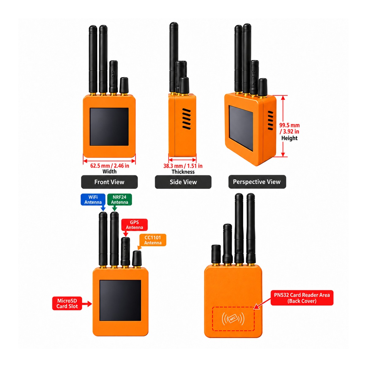
- No application firmware is pre-installed. Users must select, configure, compile and flash firmware for their own projects.
- GPS and PN532 are pre-installed inside the enclosure. No additional installation or soldering is normally required.
- Battery inclusion depends on the selected SKU. The enclosure supports a compatible 523450-size 3.7V lithium battery.
- Disconnect the internal GPS connection before firmware flashing. GPIO1 is shared with the CH340C USB-to-Serial interface and the GPS data line.
- RF module configuration depends on the selected SKU.
Product Overview
The ESP32-2432S028R-PLUS RF-HAT is a multifunctional ESP32-WROOM-32UE development platform for embedded systems, RF experimentation, wireless communication, GPS applications, NFC/RFID projects, touch-screen interfaces, IoT development and custom firmware.
The platform combines a 2.8-inch ST7789 resistive touch display system with an RF expansion board, built-in GPS and PN532 modules, MicroSD / TF storage and dedicated expansion connections.
Key Features
- ESP32-WROOM-32UE module
- IPEX1 external antenna connector
- 2.8-inch ST7789 resistive touch display
- 240 × 320 resolution
- XPT2046 resistive touch controller
- Built-in GPS module
- Built-in PN532 NFC / RFID module
- CC1101 RF expansion support depending on SKU
- NRF24L01+ PA/LNA expansion support depending on SKU
- MicroSD / TF card slot
- USB Type-C with CH340C USB-to-Serial
- Native ESP32 GPIO connections
- ZH1.5 16-pin main-board / expansion-board interconnect
- 1.25mm 2P battery interface
- RESET and BOOT functions
- Arduino IDE, PlatformIO, VS Code and LVGL development
3D Printed Enclosure
The product is supplied as an assembled unit with a fitted 3D printed enclosure. The main board, RF expansion board, GPS and PN532 are installed inside the enclosure.
Development GPIO Quick Reference
| Function | GPIO | Notes |
|---|---|---|
| LCD SCK | GPIO14 | ST7789 SPI |
| LCD MISO | GPIO12 | ST7789 SPI |
| LCD MOSI | GPIO13 | ST7789 SPI |
| LCD CS | GPIO15 | Chip Select |
| LCD DC / RS | GPIO2 | Data / Command |
| LCD Backlight | GPIO21 | PWM brightness control |
| LCD RESET | ESP32 EN | Shared with ESP32 reset |
| Touch SCK | GPIO25 | XPT2046 |
| Touch MISO | GPIO39 | Input only |
| Touch MOSI | GPIO32 | XPT2046 |
| Touch CS | GPIO33 | XPT2046 |
| Touch IRQ | GPIO36 | Input only |
| Shared SPI SCK | GPIO18 | TF / RF expansion / PN532 shared bus |
| Shared SPI MISO | GPIO19 | TF / RF expansion / PN532 shared bus |
| Shared SPI MOSI | GPIO23 | TF / RF expansion / PN532 shared bus |
| TF Card CS | GPIO5 | MicroSD / TF chip select |
| CC1101 / E07 CSN | GPIO27 | RF chip select |
| CC1101 / E07 GDO0 | GPIO22 | Input |
| CC1101 / E07 GDO2 | GPIO35 | Input only |
| E07 TX_EN | GPIO4 | RF control |
| E07 RX_EN | GPIO0 | Also ESP32 BOOT pin |
| NRF24 CSN | GPIO26 | NRF24L01+ PA/LNA |
| NRF24 CE | GPIO16 | NRF24L01+ PA/LNA |
| PN532 SS / CS | GPIO17 | PN532 SPI polling mode |
| GPS TX → ESP32 RX | GPIO1 | Shared with CH340C UART |
| UART0 RX | GPIO3 | CH340C serial connection |
| Battery ADC | GPIO34 | Input only |
Display Configuration
The 2.8-inch display uses an ST7789 controller with a 240 × 320 resolution. Firmware initialization must use BGR color order with display inversion disabled.
RF Expansion & Shared SPI Bus
The TF card, RF expansion devices and PN532 share the SPI bus on GPIO18 / GPIO19 / GPIO23. Each device uses its own chip-select line.
Built-in PN532 NFC / RFID
The built-in PN532 is connected in SPI mode using SCK=GPIO18, MISO=GPIO19, MOSI=GPIO23 and SS/CS=GPIO17. PN532 IRQ and RST are not routed to the expansion interface, so firmware should use SPI polling mode.
Built-in GPS & USB Serial
The built-in GPS provides positioning data to the ESP32 through GPIO1. GPIO1 is also used by the CH340C USB-to-Serial path, so the GPS and USB serial interface share this signal.
GPIO / Electrical Notes
- All GPIO logic levels are 3.3V. Do not apply 5V directly to GPIO pins.
- GPIO34, GPIO35, GPIO36 and GPIO39 are input-only.
- GPIO6 through GPIO11 are used internally by the ESP32 module Flash and are not available as general-purpose external GPIO.
- GPIO0 is also the BOOT strap pin and must not be held low during normal power-up/reset.
- GPIO0, GPIO2, GPIO5, GPIO12 and GPIO15 are boot-related pins. External hardware should not force incorrect levels during startup.
- GPIO18, GPIO19 and GPIO23 are shared by the TF card and expansion SPI devices.
Battery Interface & Monitoring
The board provides a 1.25mm 2P BAT interface. Battery inclusion depends on the selected SKU.
| BAT Left | Positive (+) |
| BAT Right | Negative (-) |
The enclosure supports a compatible 523450-size 3.7V lithium battery. GPIO34 is connected to the battery voltage sensing circuit through an approximately 1:2 resistor divider. Software should be calibrated against the actual ADC reference and measured battery voltage.
The board uses a TP4056 charging circuit. If charging through the board, use a suitable 5V / 1A power adapter.
Recommended Initialization Order
- Allow ESP32 boot to complete normally.
- Set all external module chip-select lines high.
- Initialize LCD SPI: SCK=14, MISO=12, MOSI=13.
- Initialize XPT2046: SCK=25, MISO=39, MOSI=32.
- Initialize shared TF / expansion SPI: SCK=18, MISO=19, MOSI=23.
- Pull low only the CS line of the device currently being accessed.
- Initialize RF control signals such as TX_EN and RX_EN last.
Firmware & Development
No application firmware is pre-installed. Users are responsible for selecting, configuring, compiling and flashing firmware suitable for their own projects.
Development environments may include:
- Arduino IDE
- PlatformIO
- VS Code
- LVGL-based projects
- Custom ESP32 firmware
- Compatible open-source ESP32 projects
Package Contents
- 1 × ESP32-2432S028R-PLUS RF-HAT assembled main unit
- 1 × USB data cable
- 1 × Compatible 523450-size 3.7V lithium battery — included only with battery-equipped SKUs
ESP32-WROOM-32UE version only.
GPS and PN532 are built into the assembled unit.
Battery inclusion depends on the selected SKU.
Disconnect the internal GPS connection before firmware flashing.
Package: 1 × assembled main unit + 1 × USB data cable, plus battery only on battery-equipped SKUs.