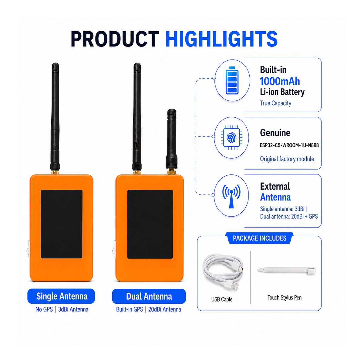
ZLX-ESP32-2
ESP32-C5 Placa de desarrollo de pantalla táctil de 2,8 pulgadas
1. Descripción general del producto
ZLX-ESP32-2 es una placa de desarrollo táctil resistiva de 2,8 pulgadas basada en el módulo ESP32-C5-WROOM-1U-N8R8. Integra una pantalla LCD a color, controlador táctil XPT2046, ranura para tarjeta microSD/TF (solo ranura para tarjeta, tarjeta microSD/TF no incluida), interfaz GPS, salida de audio, detección de voltaje de la batería, indicador LED verde, botón BOOT/RESET e interfaz de antena externa. Es adecuado para Wi-Fi 6, Bluetooth LE, Zigbee/Thread, interfaz hombre-máquina (HMI), registro de datos y desarrollo de Internet de las cosas (IoT).
Características principales
- ESP32-C5 CPU de un solo núcleo RISC-V de 32 bits, hasta 240 MHz
- ESP32-C5-WROOM-1U-N8R8: 8 MB Flash + 8 MB PSRAM (memoria del módulo integrado, no tarjeta microSD/TF)
- Wi-Fi 6 de doble banda de 2,4 GHz + 5 GHz (802.11ax)
- Bluetooth LE、IEEE 802.15.4、Zigbee 3.0、Thread 1.4
- Pantalla LCD de 2,8 pulgadas 240 × 320, chip controlador ST7789, inicialización BGR, función de inversión de pantalla desactivada
- Controlador táctil resistivo XPT2046
- La tarjeta LCD y TF comparten una interfaz SPI, pero la interfaz CS es diferente; la función táctil utiliza una interfaz SPI de software independiente.
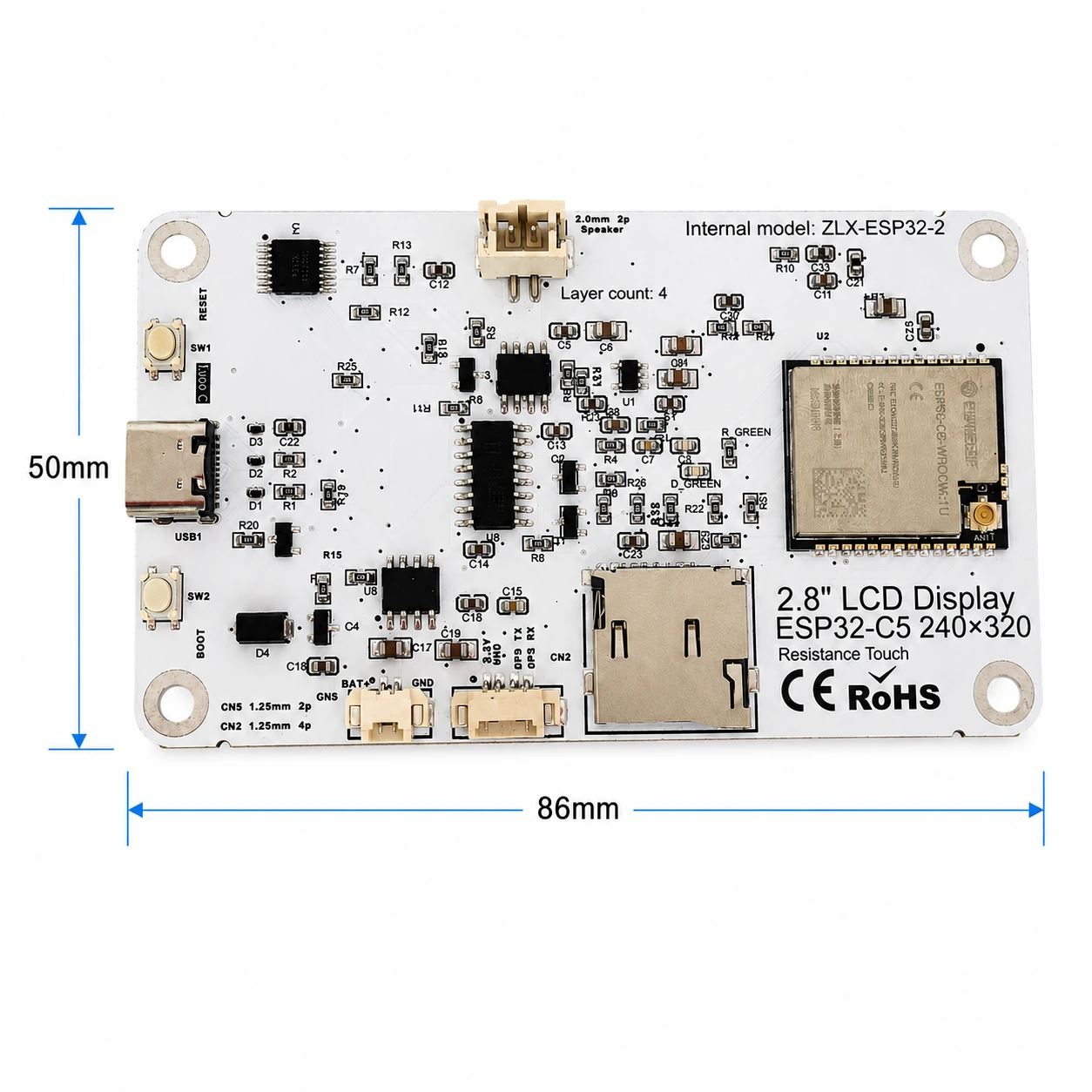
- Las dimensiones del panel son aproximadamente 86 mm x 50 mm.
- Interfaz de antena externa IPEX1; conecte una antena externa adecuada antes de usar la radio.
usuarios objetivo
Ideal para desarrolladores integrados, desarrolladores de IoT, creadores, uso educativo/laboratorio y creación de prototipos de productos.
2. Aspecto y tamaño
Las dimensiones del tablero son aproximadamente 86 mm × 50 mm. El siguiente diagrama ayuda a identificar la pantalla, los conectores y los componentes principales.
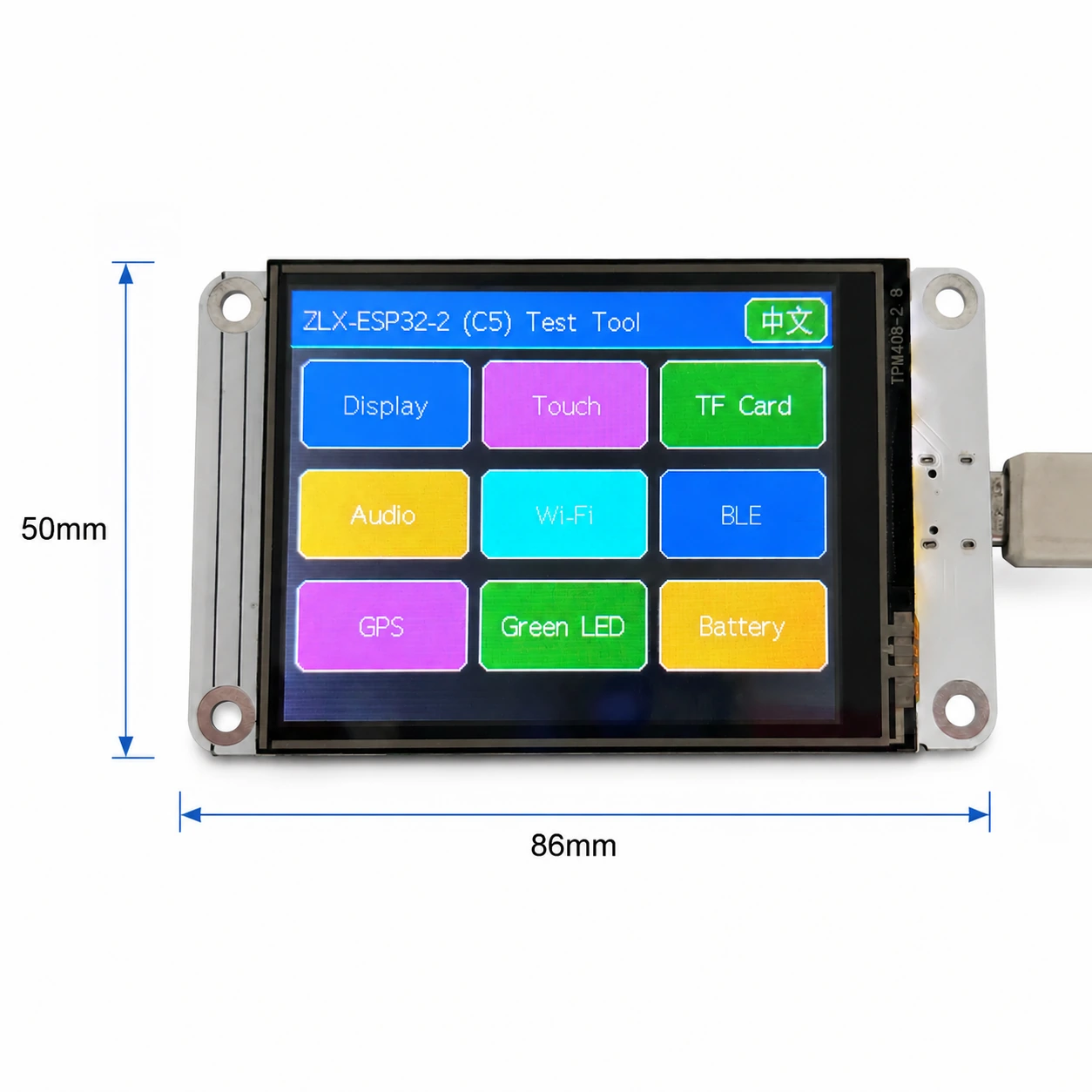
Identificación del conector
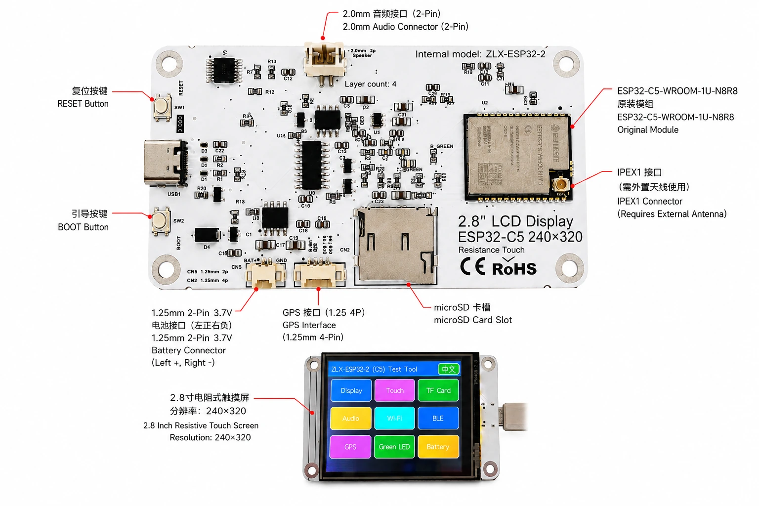
3. Especificaciones de la placa de circuito
| cosa | Especificación |
|---|---|
| modelo de placa | ZLX-ESP32-2 |
| módulo central | ESP32-C5-WROOM-1U-N8R8 |
| Tamaño del tablero | Aprox. 86 × 50 milímetros |
| anexo | Pantalla TFT LCD de 2,8 pulgadas, chip ST7789, resolución original 240×320 |
| orden de color | Inicialización de BGR |
| Pantalla invertida | Modo de visualización apagado/normal |
| tocar | Toque resistivo, XPT2046 |
| Ranura para tarjeta microSD/TF | modo SPI; tarjeta no incluida |
| Interfaz GPS | Conector de 4 pines de 1,25 mm; Señales UART en GPIO0/GPIO9 |
| vocal | Conector de audio/altavoz de 2,0 mm y 2 pines; Audio PWM + amplificador habilitado |
| Pila eléctrica | 3,7 V monofásico, doble pin de 1,25 mm; con circuito de protección, capacidad recomendada 1000–3000mAh |
| antena externa | conector IPEX1; requerido para la ruta inalámbrica WROOM-1U |
| botón | restablecer, iniciar |
| índice | LED verde en GPIO26 |
4. Especificaciones del módulo ESP32-C5-WROOM-1U-N8R8
Los siguientes parámetros clave se basan en la hoja de datos oficial de Espressif ESP32-C5-WROOM-1 / WROOM-1U v1.2.
| cosa | Especificación |
|---|---|
| SoC integrado | ESP32-C5HR8 |
| UPC | Procesador de un solo núcleo RISC-V de 32 bits, hasta 240 MHz |
| memoria de solo lectura | 320 KB |
| HP SRAM | 384 KB |
| LP SRAM | 16 KB |
| destello | SPI cuádruple de 8 MB |
| PSRAM | SPI cuádruple de 8 MB |
| Wi-Fi | 1T1R, doble banda 2,4 GHz + 5 GHz; IEEE 802.11ax/ac/b/g/n; hasta 150Mbps |
| Frecuencia de 2,4 GHz | 2412–2484 MHz |
| Frecuencia de 5GHz | 5180–5885 MHz (sujeto a regulaciones regionales) |
| bluetooth | Bluetooth de baja energía; La lista de funciones de Espressif v1.2 muestra la certificación Bluetooth Core 6.0 |
| IEEE 802.15.4 | 2.4 GHz OQPSK,250 Kbps |
| Zigbee/Thread | Zigbee 3.0 / Thread 1.4 |
| GPIO | Hay hasta 22 GPIO disponibles a nivel de módulo. |
| Typical Peripherals | GPIO, SPI, UART, I2C, I2S, RMT, LED PWM, USB Serial/JTAG, MCPWM, GDMA, CAN FD, SDIO slave, ADC, temperature sensor, timers, watchdogs, etc. |
| Module Supply | 3.0–3.6 V, typical 3.3 V |
| Recommended Supply Capability | External supply should be capable of at least 0.6 A for the module |
| Ambient Temperature | -40 to +85 °C |
| Module Size | 18.0 × 21.2 × 3.3 mm |
| Antenna | External antenna via connector/module RF path; 50 Ω RF system |
5. Display and Touch
LCD Parameters
| Item | Specification |
|---|---|
| Size | 2.8 inch |
| Driver IC | ST7789 |
| Native resolution | 240 × 320 |
| Landscape logical resolution | 320 × 240 (depending on rotation setting) |
| Color order | BGR |
| Inversion | Disabled / OFF; normal display mode |
| SPI SCK | GPIO6 |
| SPI MOSI | GPIO7 |
| SPI MISO | GPIO2 (shared with TF card; used if required by library/readback) |
| LCD CS | GPIO10 |
| LCD Backlight | GPIO13 |
| LCD DC / RS | GPIO14 |
Touch Parameters
- Touch type: 4-wire resistive; controller: XPT2046.
- DOUT=GPIO3, SCK=GPIO4, DIN=GPIO5.
- CS=GPIO23, IRQ=GPIO25.
- Touch uses an independent software SPI; the supplied test flow is marked as requiring no calibration.
6. GPIO Mapping
The mapping below is based on the supplied GPIO spreadsheet and cross-checked against the schematic. Board peripherals use 19 GPIOs; TX0=GPIO11 and RX0=GPIO12 are additionally used by UART0; GPIO15 is reserved by PSRAM on N8R8, so all 21 usable GPIOs are allocated; EN is not a GPIO.
| GPIO | Signal | Definition | Direction | Function | Notes |
|---|---|---|---|---|---|
| 0 | GPSTX | GPS UART TX | Input | GPS test | GPS module TX → ESP32-C5 |
| 1 | BAT_ADC | Battery voltage sensing | Input/ADC | Battery test | 100k/100k divider; ADC × 2 ≈ battery voltage |
| 2 | SD_MISO | TF DAT0 / LCD MISO shared | Input | TF card test | Shared SPI MISO |
| 3 | RTP_DOUT | XPT2046 DOUT | Input | Touch test | Touch controller data output |
| 4 | RTP_SCK | XPT2046 SCK | Output | Touch test | Independent software SPI |
| 5 | RTP_DIN | XPT2046 DIN | Output | Touch test | Independent software SPI |
| 6 | LCD_SCK | LCD SCK / TF SCK shared | Output | LCD/TF test | Shared SPI clock |
| 7 | LCD_MOSI | LCD MOSI / TF CMD(MOSI) shared | Output | LCD/TF test | Shared SPI MOSI |
| 8 | AUDIOPWM | Audio PWM | Output | Audio test | Audio output control |
| 9 | GPSRX | GPS UART RX | Output | GPS test | ESP32-C5 TX → GPS module RX |
| 10 | LCDCS | ST7789 CS | Output | Display test | LCD chip select |
| 13 | LCDBL | LCD backlight | Output | Display test | Backlight control |
| 14 | LCD_RS/DC | ST7789 DC | Output | Display test | Data/command select |
| 23 | RTPCS | XPT2046 CS | Output | Touch test | Touch chip select |
| 24 | AMP_EN | Amplifier enable | Output | Audio test | High-level enable per supplied mapping; verify actual hardware revision |
| 25 | RTPIRQ | XPT2046 IRQ | Input | Touch test | Touch interrupt |
| 26 | GREENLED | Green LED | Output | LED test | HIGH = ON, LOW = OFF |
| 27 | SDCS | TF DAT3 / CS | Output | TF card test | TF card SPI chip select |
| 28 | BOOTAUTO | BOOT / auto-start control | Input/Control | Factory restore | BOOT input / factory-restore logic |
System and UART Signals
| Signal | Purpose | Note |
|---|---|---|
| RESET_AUTO / EN | ESP32 reset / enable | System enable/reset; not a GPIO |
| UART0_TX / TX0 / GPIO11 | UART0 transmit | Used; excluded from the 19 peripheral GPIO count |
| UART0_RX / RX0 / GPIO12 | UART0 receive | Used; excluded from the 19 peripheral GPIO count |
7. Interface and Bus Sharing
| Item | GPIO | Description |
|---|---|---|
| LCD + TF Shared SPI | GPIO6 / GPIO7 / GPIO2 | SCK, MOSI, MISO shared; devices separated by independent CS |
| LCD CS | GPIO10 | LCD_CS |
| TF card CS | GPIO27 | SD_CS / DAT3 |
| XPT2046 touch | GPIO3 / 4 / 5 / 23 / 25 | DOUT / SCK / DIN / CS / IRQ |
| GPS UART | GPIO0 / GPIO9 | GPSTX / GPSRX; GPIO0 receives GPS TX, GPIO9 drives GPS RX |
| Battery ADC | GPIO1 | BAT_ADC; 100k/100k divider; C20 100 nF filtering |
| Green LED | GPIO26 | HIGH ON, LOW OFF |
| Audio | GPIO8 / GPIO24 | AUDIOPWM / AMP_EN |
| LCD control | GPIO13 / GPIO14 | Backlight / DC |
SPI Sharing Notes
- LCD and TF card share GPIO6 (SCK), GPIO7 (MOSI), and GPIO2 (MISO), but use GPIO10 (LCD_CS) and GPIO27 (SD_CS) respectively.
- Assert only the target device CS at a time to avoid bus contention.
- The XPT2046 touch controller uses an independent software SPI and does not share the main LCD/TF SCK/MOSI signals.
8. Functional Test Mapping
| Test | GPIO | What is tested | Result / Note |
|---|---|---|---|
| Display | GPIO6, 7, 10, 13, 14, 2 | ST7789 display, 240×320 native / 320×240 landscape; BGR; backlight | Normal / Abnormal |
| Touch | GPIO3, 4, 5, 23, 25 | XPT2046 touch response | Test flow: no calibration |
| TF card | GPIO2, 6, 7, 27 | SPI init, read/write/format | Shares SPI with LCD |
| Audio | GPIO8, 24 | PWM audio and amplifier enable | Continuous playback depends on firmware |
| Wi-Fi | Internal RF | 2.4 GHz / 5 GHz scan | No listed GPIO occupied |
| BLE | Internal RF | BLE scan | No listed GPIO occupied |
| GPS | GPIO0, 9 | GPS UART data | GPSTX / GPSRX |
| LED | GPIO26 | Green LED | HIGH on / LOW off |
| Battery | GPIO1 | ADC measures divided battery voltage | Voltage estimate, not a coulomb counter |
| Factory restore | GPIO28 | BOOT input / restore logic | Behavior is defined by firmware |
9. Connector and Electrical Notes
Battery Connector
The board provides a 1.25 mm 2-pin connector for a single-cell 3.7 V battery. In the orientation shown in the labeled image, the left pin is positive (+) and the right pin is negative (-). For battery-powered operation, use a protected single-cell 3.7 V Li-ion/LiPo battery; 1000–3000 mAh is recommended. Verify connector type and polarity before connection. Reverse polarity may damage the board.
Battery Voltage Sensing
GPIO1 senses battery voltage through a 100 kΩ / 100 kΩ divider, so ideally the battery voltage is approximately 2× the ADC pin voltage. This is a voltage estimate only and is not a fuel-gauge/coulomb-counter measurement.
GPS Interface
GPS uses GPIO0 and GPIO9 as UART signals. In this board mapping, GPIO0 (named GPSTX) is an input connected to the GPS module TX, while GPIO9 (named GPSRX) is an output connected to the GPS module RX. For the 1.25 mm 4-pin connector power pins and exact physical pin order, follow the silkscreen/schematic of the specific hardware revision.
External Antenna
ESP32-C5-WROOM-1U is the external-antenna variant. Connect a suitable 2.4/5 GHz, 50-ohm antenna to the IPEX1 connector. Avoid prolonged high-power transmission without a proper antenna attached.
Audio Connector
Audio output uses GPIO8 (AUDIOPWM) for the PWM signal and GPIO24 (AMP_EN) for amplifier enable. The top connector is a 2.0 mm 2-pin audio/speaker connector. Use loads and volume settings within the capability of the actual amplifier circuit.
10. Software Development and Initialization Notes
- Select ST7789 as the display driver and use 240×320 as the native resolution; set rotation for 320×240 landscape as supported by your graphics library.
- Use BGR color order; do not enable display inversion (INVON).
- When LCD and TF share SPI, manage LCD_CS (GPIO10) and SD_CS (GPIO27) independently after initialization.
- El XPT2046 utiliza software independiente SPI en GPIO3/4/5/23/25.
- Para el voltaje de la batería, convierta la lectura del ADC GPIO1 usando una relación de divisor de voltaje de aproximadamente 2:1 y aplique la calibración del ADC para una mayor precisión.
- Los canales Wi-Fi de 5 GHz disponibles y la potencia de transmisión dependen de las regulaciones locales.
- El comportamiento de arranque/restablecimiento de fábrica está definido por el firmware; Evite la activación accidental para evitar borrar la configuración.
Secuencia de inicialización recomendada
- Una vez que la fuente de alimentación esté estable, inicialice el sistema y depure el UART.
- Inicializar LCD SPI; configure ST7789, BGR, desactive la inversión y habilite la luz de fondo.
- Inicialice el toque XPT2046.
- Si se requiere almacenamiento extraíble, inserte una tarjeta microSD/TF compatible proporcionada por el usuario, luego inicialícela y asegúrese de que el estado LCD_CS/SD_CS sea correcto.
- Inicialice el GPS, el audio, el LED y el ADC de la batería según sea necesario.
- Habilite la funcionalidad de radio Wi-Fi/BLE/802.15.4 según sea necesario.
11. Solución de problemas
| pregunta | solución |
|---|---|
| Mostrar pantalla en blanco/negro | Verifique GPIO6/7/10/13/14, selección del controlador ST7789, configuración de BGR, retroiluminación GPIO13 y si la función de inversión se habilita accidentalmente. |
| color equivocado | Verifique que la biblioteca de gráficos esté configurada para el orden de color BGR. |
| Sin respuesta táctil | Verifique la inicialización de GPIO3/4/5/23/25 y XPT2046. |
| La inicialización de la tarjeta TF falló | Verifique SPI SCK/MOSI/MISO compartido y asegúrese de que SD_CS (GPIO27) y LCD_CS (GPIO10) no estén configurados al mismo tiempo. |
| Señal de Wi-Fi débil/sin Wi-Fi | Verifique que la antena externa IPEX1 esté conectada y sea adecuada para la banda de 2,4/5 GHz. |
| La lectura de la batería es aproximadamente la mitad. | GPIO1 utiliza un divisor de voltaje de 100k/100k; multiplique el voltaje del lado ADC por aproximadamente 2. |
| Sin datos GPS | Verifique que GPIO0 reciba GPS TX, GPIO9 controle GPS RX y verifique la velocidad en baudios y la potencia. |
12. Descargas y soporte técnico
Para obtener firmware, archivos, documentación de seguimiento y soporte relacionado del ZLX-ESP32-2, visite el Centro de soporte de la placa de desarrollo ZLX ESP32. Antes de actualizar el firmware, asegúrese de confirmar que el modelo de PCB que se muestra en el sitio web coincide exactamente con su hardware.
Enlace de descarga:https://www.zlxchina.xyz/
Ficha técnica del módulo Espressif: Ficha técnica ESP32-C5-WROOM-1 / WROOM-1U
referirse a
- Centro de soporte de la placa de desarrollo ZLX ESP32
- Espressif ESP32-C5-WROOM-1 y WROOM-1U Hoja de datos v1.2 (2026-08-12)
13. Seguridad y Operación
- Confirme la polaridad de la batería antes de conectarla; No conecte los conectores de la batería al revés.
- Al enchufar o desenchufar el conector IPEX, aplique fuerza vertical y evite hacer palanca lateral para evitar dañar el enchufe RF.
- Cuando utilice placas de circuito expuestas, tome medidas de protección contra descargas electrostáticas y evite cortocircuitos causados por objetos metálicos.
- La banda de radio de 5 GHz, el canal y la potencia de transmisión deben cumplir con las regulaciones locales.
- Para tarjetas TF, GPS, audio y otros periféricos, siga los niveles lógicos y de suministro de energía especificados por la versión real del hardware. No aplique niveles lógicos superiores a 3,3 V a los pines de E/S a menos que se verifique explícitamente.
14. Historial de revisión de documentos
| sacerdote | fecha | describir | Base |
|---|---|---|---|
| V1.1 | 2026-08-25 | Instrucciones revisadas para tarjeta microSD/TF, batería y GPIO. | Hefei Zhiluxing Tecnología de la información Co., Ltd. |
-Fin-