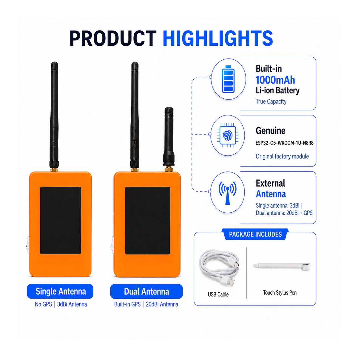
ZLX-ESP32-2
ESP32-C5 2.8 "Touch Display Development Board
1. Product Overview
The ZLX-ESP32-2 is a 2.8-inch resistive touch development board based on the ESP32-C5-WROOM-1U-N8R8 module. It integrates a color LCD display, XPT2046 touch controller, microSD/TF card slot (card slot only, excluding microSD/TF card), GPS interface, audio output, battery voltage detection, green LED indicator, boot/reset button, and external antenna interface. It is suitable for Wi-Fi 6, Bluetooth LE, Zigbee/Thread, Human Machine Interface (HMI), Data Logging, and Internet of Things (IoT) development.
Main features
- ESP32-C5 32-bit RISC-V Single Core CPU @ 240 MHz
- ESP32-C5-WROOM-1U-N8R8: 8 MB Flash + 8 MB PSRAM (onboard module memory, non-microSD/TF card)
- 2.4 GHz + 5 GHz dual-band Wi-Fi 6 (802.11ax)
- Bluetooth LE、IEEE 802.15.4、Zigbee 3.0、Thread 1.4
- 2.8 inch 240 × 320 LCD display, ST7789 driver chip, BGR initialization, display inversion function is disabled
- XPT2046 Resistive Touch Controller
- The LCD and TF card share one SPI interface, but the CS interface is different; the touch function uses a separate software SPI interface.
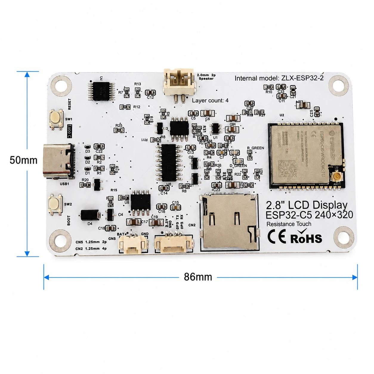
- Sheet size approx. 86mm x 50mm
- IPEX1 external antenna interface; connect the appropriate external antenna before using the radio.
Target users
For embedded developers, IoT developers, makers, educational/lab uses, and product prototyping.
2. Appearance and dimensions
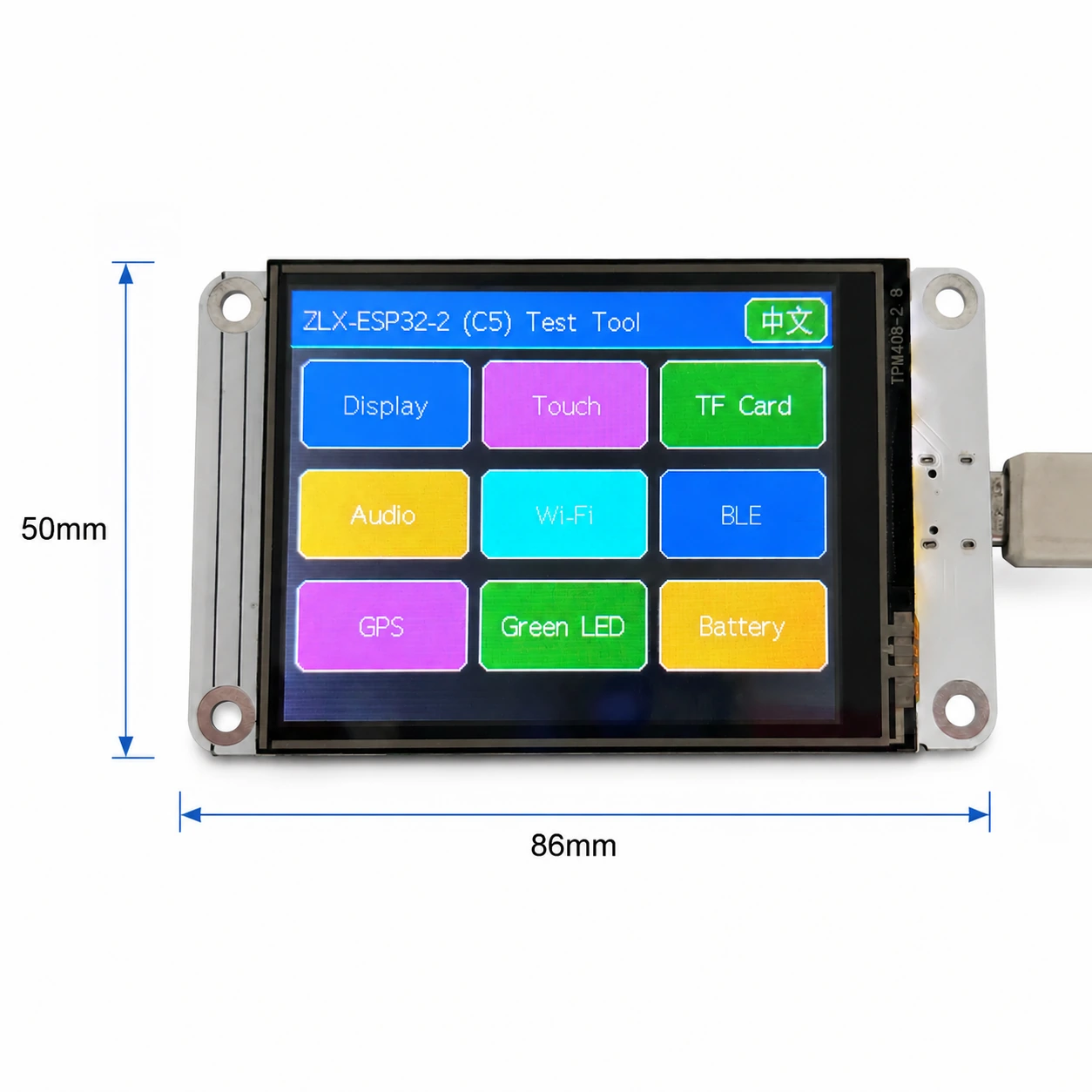
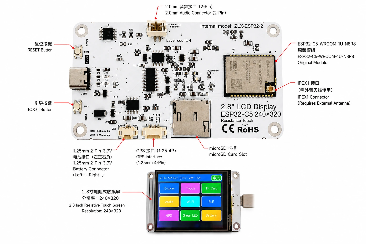
The board size is approximately 86mm x 50mm. The image below helps to identify the display, connectors and main components.
Connector Identification
3. Circuit board specifications
| Item | Specification |
|---|---|
| Plate Model | ZLX-ESP32-2 |
| Core Module | ESP32-C5-WROOM-1U-N8R8 |
| Plate size | Approx. 86 x 50 mm |
| View | 2.8 "TFT LCD, ST7789 chip, original resolution 240 × 320 |
| color order | BGR Initialization |
| Show Inverted | Off/Normal Display Mode |
| Touch | Resistive touch XPT2046 |
| microSD/TF card slot | SPI mode; card not included |
| GPS Interface | 1.25 mm 4-pin connector; UART signal on GPIO0/GPIO9 |
| acoustic | 2.0 mm 2-pin speaker/audio connector; PWM audio + amplifier enabled |
| Battery | 3.7V single phase, 1.25 mm dual pin; with protection circuit, recommended capacity 1000–3000mAh |
| external antenna | IPEX1 connector; required for WROOM-1U wireless path |
| Buttons | Reset, startup |
| Specifications | Green LED on GPIO26 |
4. ESP32-C5-WROOM-1U-N8R8 Module Specifications
The following key parameters are based on Espressif official ESP32-C5-WROOM-1/WROOM-1U datasheet v1.2.
| Item | Specification |
|---|---|
| Embedded SoCs | ESP32-C5HR8 |
| Central processing unit | 32-bit RISC-V single-core processor at up to 240 MHz |
| read-only memory | 320 KB |
| HP SRAM | 384 KB |
| LP SRAM | 16 KB |
| Blink | 8 MB Quad Channel SPI |
| PSRAM | 8 MB Quad Channel SPI |
| Wireless LAN | 1T1R, 2.4 GHz + 5 GHz dual band; IEEE 802.11ax/ac/b/g/n; up to 150 Mbps |
| 2.4 GHz Frequency | 2412–2484 MHz |
| 5 GHz frequency | 5180–5885 MHz (subject to local regulations) |
| Bluetooth | Bluetooth Low Energy; Espressif v1.2 feature list shows certified Bluetooth Core 6.0 |
| IEEE 802.15.4 | 2.4 GHz OQPSK,250 Kbps |
| Zigbee/Thread | Zigbee 3.0 / Thread 1.4 |
| GPIO | Up to 22 GPIOs are available at the module level. |
| Typical Peripherals | GPIO, SPI, UART, I2C, I2S, RMT, LED PWM, USB Serial/JTAG, MCPWM, GDMA, CAN FD, SDIO slave, ADC, temperature sensor, timers, watchdogs, etc. |
| Module Supply | 3.0–3.6 V, typical 3.3 V |
| Recommended Supply Capability | External supply should be capable of at least 0.6 A for the module |
| Ambient Temperature | -40 to +85 °C |
| Module Size | 18.0 × 21.2 × 3.3 mm |
| Antenna | External antenna via connector/module RF path; 50 Ω RF system |
5. Display and Touch
LCD Parameters
| Item | Specification |
|---|---|
| Size | 2.8 inch |
| Driver IC | ST7789 |
| Native resolution | 240 × 320 |
| Landscape logical resolution | 320 × 240 (depending on rotation setting) |
| Color order | BGR |
| Inversion | Disabled / OFF; normal display mode |
| SPI SCK | GPIO6 |
| SPI MOSI | GPIO7 |
| SPI MISO | GPIO2 (shared with TF card; used if required by library/readback) |
| LCD CS | GPIO10 |
| LCD Backlight | GPIO13 |
| LCD DC / RS | GPIO14 |
Touch Parameters
- Touch type: 4-wire resistive; controller: XPT2046.
- DOUT=GPIO3, SCK=GPIO4, DIN=GPIO5.
- CS=GPIO23, IRQ=GPIO25.
- Touch uses an independent software SPI; the supplied test flow is marked as requiring no calibration.
6. GPIO Mapping
The mapping below is based on the supplied GPIO spreadsheet and cross-checked against the schematic. Board peripherals use 19 GPIOs; TX0=GPIO11 and RX0=GPIO12 are additionally used by UART0; GPIO15 is reserved by PSRAM on N8R8, so all 21 usable GPIOs are allocated; EN is not a GPIO.
| GPIO | Signal | Definition | Direction | Function | Notes |
|---|---|---|---|---|---|
| 0 | GPSTX | GPS UART TX | Input | GPS test | GPS module TX → ESP32-C5 |
| 1 | BAT_ADC | Battery voltage sensing | Input/ADC | Battery test | 100k/100k divider; ADC × 2 ≈ battery voltage |
| 2 | SD_MISO | TF DAT0 / LCD MISO shared | Input | TF card test | Shared SPI MISO |
| 3 | RTP_DOUT | XPT2046 DOUT | Input | Touch test | Touch controller data output |
| 4 | RTP_SCK | XPT2046 SCK | Output | Touch test | Independent software SPI |
| 5 | RTP_DIN | XPT2046 DIN | Output | Touch test | Independent software SPI |
| 6 | LCD_SCK | LCD SCK / TF SCK shared | Output | LCD/TF test | Shared SPI clock |
| 7 | LCD_MOSI | LCD MOSI / TF CMD(MOSI) shared | Output | LCD/TF test | Shared SPI MOSI |
| 8 | AUDIOPWM | Audio PWM | Output | Audio test | Audio output control |
| 9 | GPSRX | GPS UART RX | Output | GPS test | ESP32-C5 TX → GPS module RX |
| 10 | LCDCS | ST7789 CS | Output | Display test | LCD chip select |
| 13 | LCDBL | LCD backlight | Output | Display test | Backlight control |
| 14 | LCD_RS/DC | ST7789 DC | Output | Display test | Data/command select |
| 23 | RTPCS | XPT2046 CS | Output | Touch test | Touch chip select |
| 24 | AMP_EN | Amplifier enable | Output | Audio test | High-level enable per supplied mapping; verify actual hardware revision |
| 25 | RTPIRQ | XPT2046 IRQ | Input | Touch test | Touch interrupt |
| 26 | GREENLED | Green LED | Output | LED test | HIGH = ON, LOW = OFF |
| 27 | SDCS | TF DAT3 / CS | Output | TF card test | TF card SPI chip select |
| 28 | BOOTAUTO | BOOT / auto-start control | Input/Control | Factory restore | BOOT input / factory-restore logic |
System and UART Signals
| Signal | Purpose | Note |
|---|---|---|
| RESET_AUTO / EN | ESP32 reset / enable | System enable/reset; not a GPIO |
| UART0_TX / TX0 / GPIO11 | UART0 transmit | Used; excluded from the 19 peripheral GPIO count |
| UART0_RX / RX0 / GPIO12 | UART0 receive | Used; excluded from the 19 peripheral GPIO count |
7. Interface and Bus Sharing
| Item | GPIO | Description |
|---|---|---|
| LCD + TF Shared SPI | GPIO6 / GPIO7 / GPIO2 | SCK, MOSI, MISO shared; devices separated by independent CS |
| LCD CS | GPIO10 | LCD_CS |
| TF card CS | GPIO27 | SD_CS / DAT3 |
| XPT2046 touch | GPIO3 / 4 / 5 / 23 / 25 | DOUT / SCK / DIN / CS / IRQ |
| GPS UART | GPIO0 / GPIO9 | GPSTX / GPSRX; GPIO0 receives GPS TX, GPIO9 drives GPS RX |
| Battery ADC | GPIO1 | BAT_ADC; 100k/100k divider; C20 100 nF filtering |
| Green LED | GPIO26 | HIGH ON, LOW OFF |
| Audio | GPIO8 / GPIO24 | AUDIOPWM / AMP_EN |
| LCD control | GPIO13 / GPIO14 | Backlight / DC |
SPI Sharing Notes
- LCD and TF card share GPIO6 (SCK), GPIO7 (MOSI), and GPIO2 (MISO), but use GPIO10 (LCD_CS) and GPIO27 (SD_CS) respectively.
- Assert only the target device CS at a time to avoid bus contention.
- The XPT2046 touch controller uses an independent software SPI and does not share the main LCD/TF SCK/MOSI signals.
8. Functional Test Mapping
| Test | GPIO | What is tested | Result / Note |
|---|---|---|---|
| Display | GPIO6, 7, 10, 13, 14, 2 | ST7789 display, 240×320 native / 320×240 landscape; BGR; backlight | Normal / Abnormal |
| Touch | GPIO3, 4, 5, 23, 25 | XPT2046 touch response | Test flow: no calibration |
| TF card | GPIO2, 6, 7, 27 | SPI init, read/write/format | Shares SPI with LCD |
| Audio | GPIO8, 24 | PWM audio and amplifier enable | Continuous playback depends on firmware |
| Wi-Fi | Internal RF | 2.4 GHz / 5 GHz scan | No listed GPIO occupied |
| BLE | Internal RF | BLE scan | No listed GPIO occupied |
| GPS | GPIO0, 9 | GPS UART data | GPSTX / GPSRX |
| LED | GPIO26 | Green LED | HIGH on / LOW off |
| Battery | GPIO1 | ADC measures divided battery voltage | Voltage estimate, not a coulomb counter |
| Factory restore | GPIO28 | BOOT input / restore logic | Behavior is defined by firmware |
9. Connector and Electrical Notes
Battery Connector
The board provides a 1.25 mm 2-pin connector for a single-cell 3.7 V battery. In the orientation shown in the labeled image, the left pin is positive (+) and the right pin is negative (-). For battery-powered operation, use a protected single-cell 3.7 V Li-ion/LiPo battery; 1000–3000 mAh is recommended. Verify connector type and polarity before connection. Reverse polarity may damage the board.
Battery Voltage Sensing
GPIO1 senses battery voltage through a 100 kΩ / 100 kΩ divider, so ideally the battery voltage is approximately 2× the ADC pin voltage. This is a voltage estimate only and is not a fuel-gauge/coulomb-counter measurement.
GPS Interface
GPS uses GPIO0 and GPIO9 as UART signals. In this board mapping, GPIO0 (named GPSTX) is an input connected to the GPS module TX, while GPIO9 (named GPSRX) is an output connected to the GPS module RX. For the 1.25 mm 4-pin connector power pins and exact physical pin order, follow the silkscreen/schematic of the specific hardware revision.
External Antenna
ESP32-C5-WROOM-1U is the external-antenna variant. Connect a suitable 2.4/5 GHz, 50-ohm antenna to the IPEX1 connector. Avoid prolonged high-power transmission without a proper antenna attached.
Audio Connector
Audio output uses GPIO8 (AUDIOPWM) for the PWM signal and GPIO24 (AMP_EN) for amplifier enable. The top connector is a 2.0 mm 2-pin audio/speaker connector. Use loads and volume settings within the capability of the actual amplifier circuit.
10. Software Development and Initialization Notes
- Select ST7789 as the display driver and use 240×320 as the native resolution; set rotation for 320×240 landscape as supported by your graphics library.
- Use BGR color order; do not enable display inversion (INVON).
- When LCD and TF share SPI, manage LCD_CS (GPIO10) and SD_CS (GPIO27) independently after initialization.
- XPT2046 uses standalone software SPI on GPIO3/4/5/23/25.
- For battery voltage, convert GPIO1 ADC readings using a partial voltage ratio of approximately 2: 1 and apply ADC calibration for higher accuracy.
- Available 5 GHz Wi-Fi channels and transmit power depend on local regulations.
- The behavior of starting/restoring factory settings is defined by the firmware; please avoid accidental activation to avoid clearing the settings.
Suggested Initialization Order
- When the power is stable, initialize the system and debug the UART.
- Initialize LCD SPI; configure ST7789, BGR, turn off inversion, and enable backlighting.
- Initialize XPT2046 touch.
- If removable storage is required, insert a compatible user-supplied microSD/TF card, then initialize it and ensure the LCD_CS/SD_CS status is correct.
- Initialize GPS, audio, LEDs, and battery ADCs as needed.
- Enable Wi-Fi/BLE/802.15.4 radio as needed.
11. Troubleshooting
| question | R&esolution |
|---|---|
| Show Blank/Black Screen | Check GPIO6/7/10/13/14, ST7789 drive selection, BGR settings, backlit GPIO13, and if inversion is accidentally enabled. |
| Color error | Verify that the graphics library is configured for BGR color order. |
| No touch response | Check initialization of GPIO3/4/5/23/25 and XPT2046. |
| TF card initialization failed | Check the shared SPI SCK/MOSI/miso and make sure that SD_CS (GPIO27) and LCD_CS (GPIO10) are not set at the same time. |
| Wi-Fi signal weak/no Wi-Fi | Verify that the IPEX1 external antenna is connected and works in the 2.4/5 GHz band. |
| About half the battery readings | GPIO1 uses a 100k/100k voltage divider; multiply the ADC side voltage by approximately 2. |
| No GPS data | Verify that GPIO0 receives GPS TX, GPIO9 drives GPS RX, and verifies baud rate and power supply. |
12. Downloads and Technical Support
For ZLX-ESP32-2 firmware, documentation, follow-up documentation, and related support, visit the ZLX ESP32 Development Board Support Center. Before flashing the firmware, make sure that the PCB model shown on the website exactly matches your hardware.
Download Link:https://www.zlxchina.xyz/
Lexin Module Data Sheet: ESP32-C5-WROOM-1/WROOM-1U Data Sheet
REFERENCE
- ZLX ESP32 Development Board Support Center
- Espressif ESP32-C5-WROOM-1 & WROOM-1U Data Sheet v1.2 (2026-08-12)
13. Safety and operation
- Check the battery polarity before connecting; never reverse the battery connector.
- When plugging and unplugging the IPEX connector, apply force vertically and avoid lateral prying to avoid damaging the RF socket.
- When using bare circuit boards, take electrostatic discharge protection measures and prevent short circuits caused by metal objects.
- 5 GHz radio bands, channels and transmit power must comply with local regulations.
- For TF cards, GPS, audio, and other peripherals, follow the power and logic levels specified in the actual hardware version. Do not apply a logic level higher than 3.3V to I/O pins unless explicitly verified.
14. Document revision history
| Cleric | date | Description | FOUNDATION |
|---|---|---|---|
| V1.1 | 2026-08-25 | Revised instructions for microSD/TF cards, batteries, and GPIO. | Hefei Zhiluxing Information Technology Co., Ltd. |
End