ZLX-ESP32-2
ESP32-C5 2.8-inch Touch Display Development Board
دليل المستخدم الصينية والإنجليزية / Bilingual User Manual
Model / النموذج: ZLX-ESP32-2
Module / وحدة: ESP32-C5-WROOM-1U-N8R8
Document Version / نسخة الوثيقة: V1.1 | 2026-08-25
1. نظرة عامة على المنتج / 1. Product Overview
ZLX-ESP32-2 هو منتج يعتمد على ESP32-C5-WROOM-1U-N8R8 وحدات 2.8 لوحة تطوير شاشة تعمل باللمس مقاومة بوصة مع لون متكامل LCD、XPT2046 يلمس،microSD/TF فتحة للبطاقات (فتحة للبطاقات فقط، غير متضمنة). microSD/TF بطاقة)،GPS واجهة، إخراج الصوت، كشف جهد البطارية، أخضر LED、BOOT/RESET زر وواجهة هوائي خارجي. مناسب Wi-Fi 6、Bluetooth LE、Zigbee/Threadوالواجهة بين الإنسان والآلة وتسجيل البيانات وتطوير تطبيقات إنترنت الأشياء.
ZLX-ESP32-2 is a 2.8-inch resistive-touch development board based on the ESP32-C5-WROOM-1U-N8R8 module. It integrates a color LCD, XPT2046 touch controller, a microSD/TF card slot (slot only; no microSD/TF card is included), GPS interface, audio output, battery-voltage sensing, green LED, BOOT/RESET buttons, and an external-antenna connector. It is suitable for Wi-Fi 6, Bluetooth LE, Zigbee/Thread, HMI, data logging, and IoT development.
الميزات الرئيسية / Key Features
ESP32-C5 32 قليل RISC-V معالج أحادي النواة يصل إلى 240 MHz / ESP32-C5 32-bit RISC-V single-core CPU, up to 240 MHz
ESP32-C5-WROOM-1U-N8R8:8 MB Flash + 8 MB PSRAM(وحدة الموارد على متن الطائرة، وليس microSD/TF بطاقة) / ESP32-C5-WROOM-1U-N8R8: 8 MB Flash + 8 MB PSRAM (onboard module memory, not a microSD/TF card)
2.4 GHz + 5 GHz الفرقة المزدوجة Wi-Fi 6(802.11ax) / 2.4 GHz + 5 GHz dual-band Wi-Fi 6 (802.11ax)
Bluetooth LE、IEEE 802.15.4、Zigbee 3.0、Thread 1.4 / Bluetooth LE, IEEE 802.15.4, Zigbee 3.0, Thread 1.4
2.8 بوصة 240×320 LCD,ST7789 يقود،BGR التهيئة، تعطيل اللون العكسي / 2.8-inch 240×320 LCD, ST7789 driver, BGR initialization, display inversion disabled
XPT2046 تحكم باللمس مقاوم / XPT2046 resistive touch controller
LCD و TF مشاركة البطاقة SPI حافلة مستقلة CS؛المس لاستخدام برنامج مستقل SPI / LCD and TF card share SPI with separate CS; touch uses an independent software SPI
حجم اللوحة تقريبًا. 86 mm × 50 mm / Board size approx. 86 mm × 50 mm
IPEX1 واجهة الهوائي الخارجي؛ يجب توصيل الهوائي الخارجي بشكل صحيح قبل استخدام الوظيفة اللاسلكية / IPEX1 external antenna connector; connect a suitable external antenna before radio use
الكائنات القابلة للتطبيق / Intended Users
مناسب للمطورين المدمجين ومطوري إنترنت الأشياء والصانعين وتجارب التدريس وتصميم النموذج الأولي للمنتج.
For embedded developers, IoT developers, makers, education/lab use, and product prototyping.
2. المظهر والحجم / 2. Appearance and Dimensions
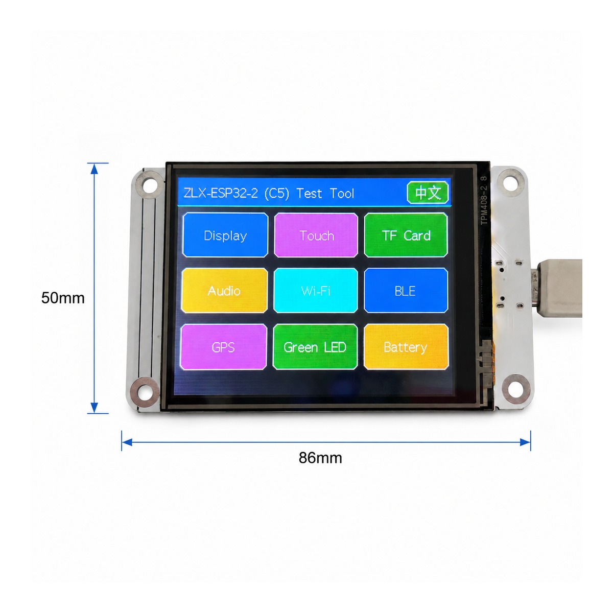
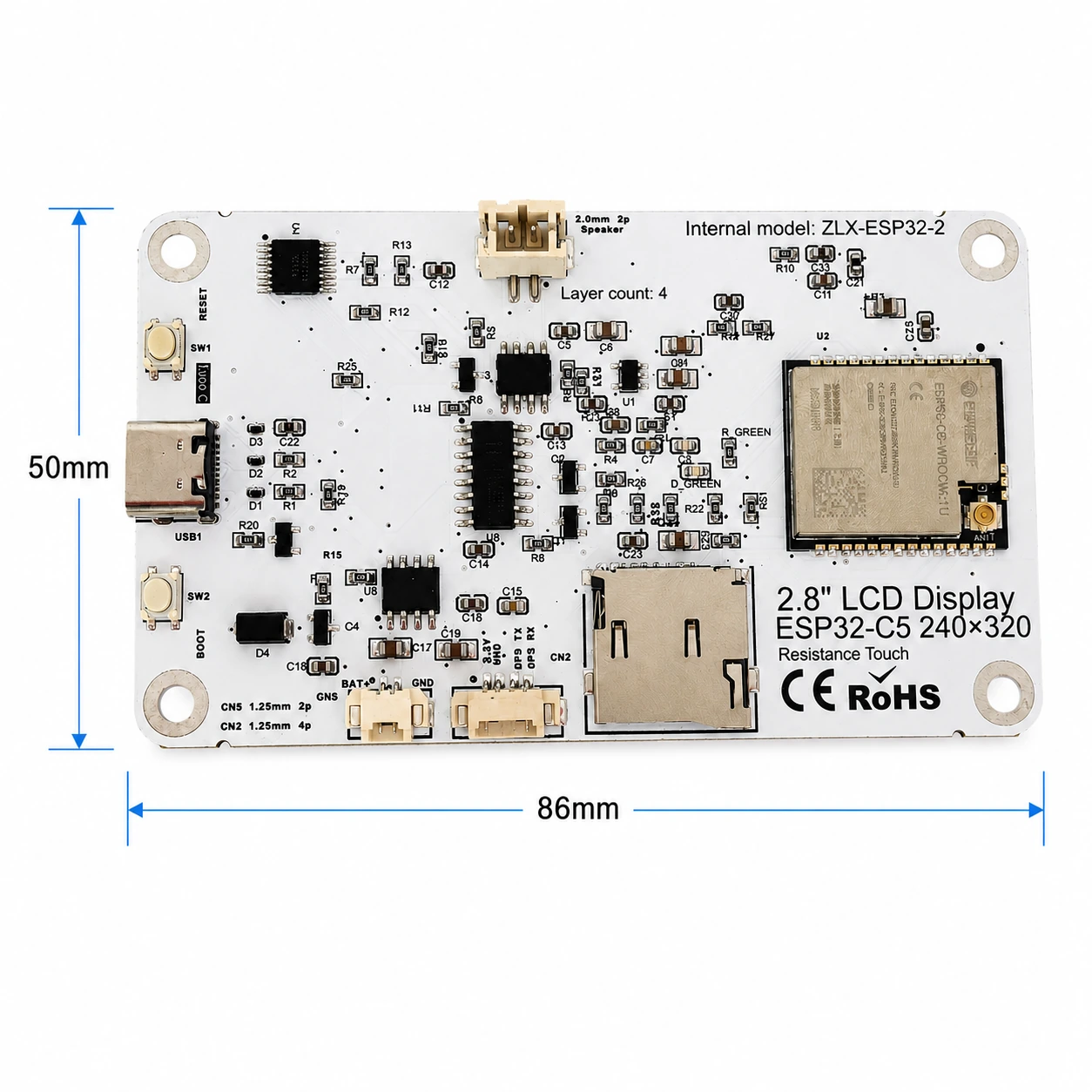
الأبعاد الكلية للمجلس تقريبًا 86 mm × 50 mm. يتم استخدام الصور الأمامية والخلفية التالية للتعرف على الشاشة والواجهات والمكونات الرئيسية.
The board outline is approximately 86 mm × 50 mm. The images below help identify the display, connectors, and major components.
|
|
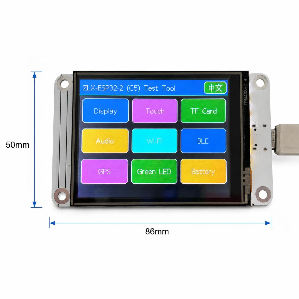
صورة 1 الأبعاد الأمامية والشاشة / Figure 1 Board front and display-side dimensions
شرح الواجهة / Connector Identification
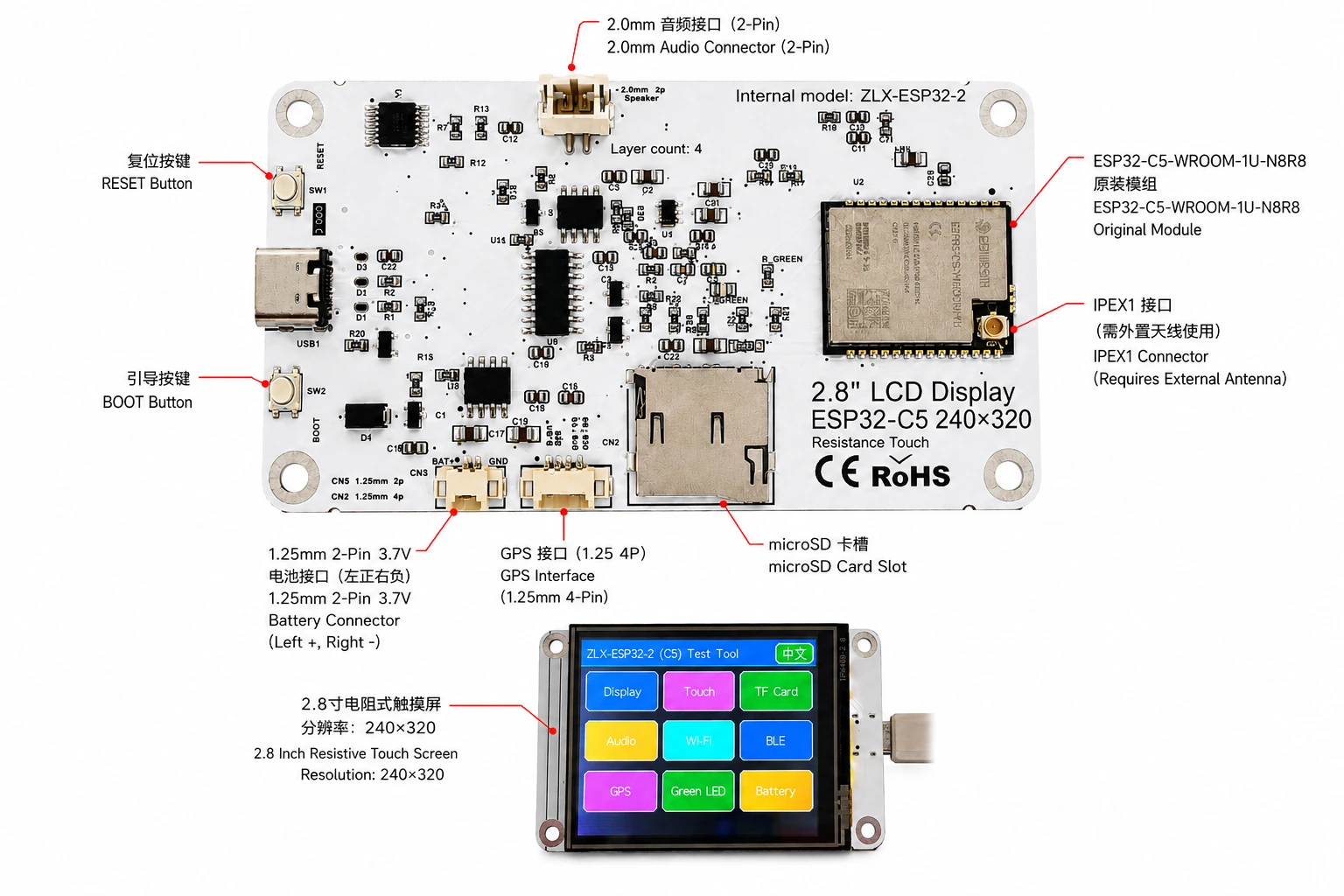
صورة 2 ZLX-ESP32-2 التعليقات التوضيحية للواجهة الصينية والإنجليزية / Figure 2 Bilingual connector identification
3. مواصفات مجلس التنمية / 3. Board Specifications
مشروع / Item | ● المواصفات / Specification |
نموذج مجلس التنمية / Board model | ZLX-ESP32-2 |
الوحدة الأساسية / Core module | ESP32-C5-WROOM-1U-N8R8 |
حجم اللوحة / Board size | Approx. 86 × 50 mm |
عرض / Display | 2.8-inch TFT LCD, ST7789, 240×320 native resolution |
ترتيب الألوان / Color order | BGR initialization |
إظهار اللون العكسي / Display inversion | OFF / Normal display mode(لا تقم بتشغيل اللون العكسي) |
يلمس / Touch | Resistive touch / لمسة مقاومة, XPT2046 |
microSD/TF فتحة البطاقة / microSD/TF Card Slot | SPI mode; card not included / SPI وضع؛ لا يأتي مع البطاقة |
GPS واجهة / GPS interface | 1.25 mm 4-pin connector; UART signals on GPIO0/GPIO9 |
واجهة الصوت / Audio | 2.0 mm 2-pin speaker/audio connector; PWM audio + amplifier enable |
واجهة البطارية / Battery | 3.7 V 1S, 1.25 mm 2-pin; protected 1000–3000 mAh recommended / قسم واحد 3.7 V؛اقتراح 1000–3000 mAh مع لوحة الحماية |
هوائي خارجي / External antenna | IPEX1 connector; required for the WROOM-1U radio path |
زر / Buttons | RESET, BOOT |
إشارة الحالة / Indicator | Green LED on GPIO26 |
يوضح / Note: دقة الشاشة الأصلية هي 240×320؛عندما يتم ضبط البرنامج على تدوير الشاشة أفقيًا، يمكن التعبير عن حجم العرض المنطقي كـ 320×240。 / The panel native resolution is 240×320; in landscape rotation, the logical display size may be 320×240.
4. ESP32-C5-WROOM-1U-N8R8 معلمات الوحدة / 4. ESP32-C5-WROOM-1U-N8R8 Module Specifications
تعتمد المعلمات الرئيسية التالية على Espressif رسمي ESP32-C5-WROOM-1 / WROOM-1U Datasheet v1.2。
The following key parameters are based on Espressif's official ESP32-C5-WROOM-1 / WROOM-1U Datasheet v1.2.
مشروع / Item | ● المواصفات / Specification |
شريحة مدمجة / Embedded SoC | ESP32-C5HR8 |
CPU | 32-bit RISC-V single core, up to 240 MHz |
ROM | 320 KB |
HP SRAM | 384 KB |
LP SRAM | 16 KB |
Flash | 8 MB Quad SPI |
PSRAM | 8 MB Quad SPI |
Wi-Fi | 1T1R, 2.4 GHz + 5 GHz dual-band; IEEE 802.11ax/ac/b/g/n; up to 150 Mbps |
2.4 GHz تكرار / Frequency | 2412–2484 MHz |
5 GHz تكرار / Frequency | 5180–5885 MHz (subject to regional regulations) |
Bluetooth | Bluetooth LE; Espressif v1.2 feature list states Bluetooth Core 6.0 certified |
IEEE 802.15.4 | 2.4 GHz OQPSK, 250 Kbps |
Zigbee / Thread | Zigbee 3.0 / Thread 1.4 |
GPIO | Up to 22 GPIOs at module level |
الأجهزة الطرفية النموذجية / Peripherals | GPIO, SPI, UART, I2C, I2S, RMT, LED PWM, USB Serial/JTAG, MCPWM, GDMA, CAN FD, SDIO slave, ADC, temperature sensor, timers, watchdogs, etc. |
وحدة العمل الجهد / Module supply | 3.0–3.6 V, typical 3.3 V |
قدرات الطاقة الموصى بها / Recommended supply capability | External supply should be capable of at least 0.6 A for the module |
درجة الحرارة المحيطة / Ambient temperature | -40 to +85 °C |
حجم الوحدة / Module size | 18.0 × 21.2 × 3.3 mm |
هوائي / Antenna | External antenna via connector/module RF path; 50 Ω RF system |
5. العرض واللمس / 5. Display and Touch
LCD المعلمة / LCD Parameters
مشروع / Item | ● المواصفات / Specification |
مقاس / Size | 2.8 inch |
يقود IC / Driver IC | ST7789 |
القرار الأصلي / Native resolution | 240 × 320 |
الدقة المنطقية للشاشة الأفقية / Landscape logical resolution | 320 × 240 (depending on rotation setting) |
ترتيب الألوان / Color order | BGR |
لون عكسي / Inversion | Disabled / OFF; normal display mode |
SPI ساعة / SCK | GPIO6 |
SPI MOSI | GPIO7 |
SPI MISO | GPIO2 (shared with TF card; used if required by library/readback) |
LCD CS | GPIO10 |
LCD Backlight / الإضاءة الخلفية | GPIO13 |
LCD DC / RS | GPIO14 |
معلمات اللمس / Touch Parameters
نوع اللمس:4 لمسة سلكية مقاومة؛ المراقب المالي:XPT2046。 / Touch type: 4-wire resistive; controller: XPT2046.
DOUT=GPIO3,SCK=GPIO4,DIN=GPIO5。 / DOUT=GPIO3, SCK=GPIO4, DIN=GPIO5.
CS=GPIO23,IRQ=GPIO25。 / CS=GPIO23, IRQ=GPIO25.
المس لاستخدام برنامج مستقل SPI؛ تم وضع علامة على عملية أداة الكشف على أنها لا تتطلب المعايرة. / Touch uses an independent software SPI; the supplied test flow is marked as requiring no calibration.
6. GPIO رسم الخرائط / 6. GPIO Mapping
التعيينات التالية مأخوذة من إصدار العميل المتوفر مع اللوحة GPIO جدول البيانات وفحصه مقابل التخطيطي. الاستخدام المحيطي على متن الطائرة 19 عادية GPIO;TX0=GPIO11、RX0=GPIO12 تستخدم أيضا ل UART0;N8R8 ل GPIO15 لحاف PSRAM المحتلة، لذلك 21 متاح GPIO تم تعيين كل شيء؛EN لا يعتبر عملا GPIO。
The mapping below is based on the supplied GPIO spreadsheet and cross-checked against the schematic. Board peripherals use 19 GPIOs; TX0=GPIO11 and RX0=GPIO12 are additionally used by UART0; GPIO15 is reserved by PSRAM on N8R8, so all 21 usable GPIOs are allocated; EN is not a GPIO.
GPIO | Signal | تعريف / Definition | اتجاه / Direction | وظيفة / Function | يوضح / Notes |
0 | GPSTX | GPS المنفذ التسلسلي TX / GPS UART TX | Input / يدخل | GPS test / GPSامتحان | GPS module TX → ESP32-C5 |
1 | BAT_ADC | كشف جهد البطارية / Battery voltage sensing | Input/ADC | Battery test | 100k/100k divider; ADC × 2 ≈ battery voltage |
2 | SD_MISO | TF DAT0 / LCD MISO يشارك / Shared | Input | TF card test | Shared SPI MISO |
3 | RTP_DOUT | XPT2046 DOUT | Input | Touch test | Touch controller data output |
4 | RTP_SCK | XPT2046 SCK | Output | Touch test | Independent software SPI |
5 | RTP_DIN | XPT2046 DIN | Output | Touch test | Independent software SPI |
6 | LCD_SCK | LCD SCK / TF SCK يشارك / Shared | Output | LCD/TF test | Shared SPI clock |
7 | LCD_MOSI | LCD MOSI / TF CMD(MOSI) يشارك / Shared | Output | LCD/TF test | Shared SPI MOSI |
8 | AUDIOPWM | صوتي PWM / Audio PWM | Output | Audio test | Audio output control |
9 | GPSRX | GPS المنفذ التسلسلي RX / GPS UART RX | Output | GPS test | ESP32-C5 TX → GPS module RX |
10 | LCDCS | ST7789 CS | Output | Display test | LCD chip select |
13 | LCDBL | LCD الإضاءة الخلفية / LCD backlight | Output | Display test | Backlight control |
14 | LCD_RS/DC | ST7789 DC | Output | Display test | Data/command select |
23 | RTPCS | XPT2046 CS | Output | Touch test | Touch chip select |
24 | AMP_EN | تم تمكين مكبر الصوت / Amplifier enable | Output | Audio test | High-level enable per supplied mapping; verify actual hardware revision |
25 | RTPIRQ | XPT2046 IRQ | Input | Touch test | Touch interrupt |
26 | GREENLED | أخضر LED / Green LED | Output | LED test | HIGH = ON, LOW = OFF |
27 | SDCS | TF DAT3 / CS | Output | TF card test | TF card SPI chip select |
28 | BOOTAUTO | BOOT / التحكم التلقائي في البدء / auto-start control | Input/Control | Factory restore | BOOT input / factory-restore logic |
إشارات النظام والمنفذ التسلسلي / System and UART Signals
إشارة / Signal | يستخدم / Purpose | ملاحظة / Note |
RESET_AUTO / EN | ESP32 reset / enable / ESP32 إعادة تعيين وتمكين | System enable/reset; not a GPIO / تمكين النظام/إعادة تعيين، لا ينتمي إلى GPIO |
UART0_TX / TX0 / GPIO11 | UART0 transmit / UART0 إرسال المنفذ التسلسلي | Used; excluded from the 19 peripheral GPIO count / مستخدم؛ لا تحسب في ما سبق 19 الأجهزة الطرفية GPIO |
UART0_RX / RX0 / GPIO12 | UART0 receive / UART0 استقبال المنفذ التسلسلي | Used; excluded from the 19 peripheral GPIO count / مستخدم؛ لا تحسب في ما سبق 19 الأجهزة الطرفية GPIO |
7. تعليمات مشاركة الواجهة والحافلة / 7. Interface and Bus Sharing
مشروع / Item | GPIO | يوضح / Description |
LCD + TF SPI يشارك / Shared SPI | GPIO6 / GPIO7 / GPIO2 | SCK, MOSI, MISO shared; devices separated by independent CS / ساعة مشتركة وخطوط بيانات، استخدمها بشكل مستقل CS التمييز بين الأجهزة |
LCD CS | GPIO10 | LCD_CS |
TF card CS | GPIO27 | SD_CS / DAT3 |
XPT2046 touch | GPIO3 / 4 / 5 / 23 / 25 | DOUT / SCK / DIN / CS / IRQ |
GPS UART | GPIO0 / GPIO9 | GPSTX / GPSRX; GPIO0 receives GPS TX, GPIO9 drives GPS RX |
Battery ADC | GPIO1 | BAT_ADC; 100k/100k divider; C20 100 nF filtering |
Green LED | GPIO26 | HIGH ON, LOW OFF |
Audio | GPIO8 / GPIO24 | AUDIOPWM / AMP_EN |
LCD control | GPIO13 / GPIO14 | Backlight / DC |
SPI اعتبارات المشاركة / SPI Sharing Notes
LCD و TF مشاركة البطاقة GPIO6(SCK)、GPIO7(MOSI)、GPIO2(MISO)ولكن باستخدام على التوالي GPIO10(LCD_CS) و GPIO27(SD_CS)。 / LCD and TF card share GPIO6 (SCK), GPIO7 (MOSI), and GPIO2 (MISO), but use GPIO10 (LCD_CS) and GPIO27 (SD_CS) respectively.
قم بتمكين الجهاز المستهدف فقط في نفس الوقت CS، لتجنب تعارضات الناقل الناتجة عن تحديد أجهزة متعددة في نفس الوقت. / Assert only the target device CS at a time to avoid bus contention.
يلمس XPT2046 استخدام البرامج المستقلة SPIوليس مع LCD/TF رب SPI الساعة و MOSI مشترك. / The XPT2046 touch controller uses an independent software SPI and does not share the main LCD/TF SCK/MOSI signals.
8. مراسلات وظيفة الكشف / 8. Functional Test Mapping
عناصر الاختبار / Test | GPIO | محتوى الكشف / What is tested | نتيجة/يوضح / Result/Note |
اختبار الشاشة / Display | GPIO6, 7, 10, 13, 14, 2 | ST7789 display, 240×320 native / 320×240 landscape; BGR; backlight | Normal / Abnormal |
اختبار اللمس / Touch | GPIO3, 4, 5, 23, 25 | XPT2046 touch response | Test flow: no calibration |
TF اختبار البطاقة / TF card | GPIO2, 6, 7, 27 | SPI init, read/write/format | Shares SPI with LCD |
اختبار الصوت / Audio | GPIO8, 24 | PWM audio and amplifier enable | Continuous playback depends on firmware |
Wi-Fi امتحان / Wi-Fi | Internal RF | 2.4 GHz / 5 GHz scan | No listed GPIO occupied |
BLE امتحان / BLE | Internal RF | BLE scan | No listed GPIO occupied |
GPS امتحان / GPS | GPIO0, 9 | GPS UART data | GPSTX / GPSRX |
LED امتحان / LED | GPIO26 | Green LED | HIGH on / LOW off |
اختبار البطارية / Battery | GPIO1 | ADC measures divided battery voltage | Voltage estimate, not a coulomb counter |
BOOT إعادة ضبط المصنع / Factory restore | GPIO28 | BOOT input / restore logic | Behavior is defined by firmware |
9. واجهة والاعتبارات الكهربائية / 9. Connector and Electrical Notes
واجهة البطارية / Battery Connector
مجلس التنمية المقدمة 1.25 mm 2-Pin 3.7 V واجهة بطارية واحدة. وفقًا لاتجاه العرض في الرسم التخطيطي المحدد، فإن الجانب الأيسر هو القطب الموجب (+) ، الجانب الأيمن هو القطب السالب (-). إذا كانت طاقة البطارية مطلوبة، فمن المستحسن استخدام السعة 1000–3000 mAhقسم واحد مع لوحة الحماية (دائرة الحماية) 3.7 V أيون الليثيوم/بطارية ليثيوم بوليمر، والتأكد من مواصفات الواجهة والأقطاب الإيجابية والسلبية قبل التوصيل. قد يؤدي الاتصال العكسي إلى إتلاف لوحة التطوير.
The board provides a 1.25 mm 2-pin connector for a single-cell 3.7 V battery. In the orientation shown in the labeled image, the left pin is positive (+) and the right pin is negative (-). For battery-powered operation, use a protected single-cell 3.7 V Li-ion/LiPo battery; 1000–3000 mAh is recommended. Verify connector type and polarity before connection. Reverse polarity may damage the board.
GPIO1 يمر 100 kΩ / 100 kΩ تكتشف شبكة مقسم الجهد جهد البطارية، لذلك في الظروف المثالية يكون جهد البطارية الفعلي تقريبًا ADC دبوس الجهد 2 مرات. هذه الوظيفة مخصصة فقط لتقدير الجهد، وليست مقياس كولوم الوقود.
GPIO1 senses battery voltage through a 100 kΩ / 100 kΩ divider, so ideally the battery voltage is approximately 2× the ADC pin voltage. This is a voltage estimate only and is not a fuel-gauge/coulomb-counter measurement.
GPS واجهة / GPS Interface
GPS يستخدم GPIO0 و GPIO9 مثل UART إشارة.GPIO0(GPSTX اسمه) كمدخل في تعريف اللوحة هذا، قم بالاتصال GPS وحدة TX;GPIO9(GPSRX اسمه) كإخراج، الاتصال GPS وحدة RX。1.25 mm 4-Pin يرجى الرجوع إلى إصدار الأجهزة المقابل لمعرفة دبابيس الطاقة وتسلسل الدبوس الفعلي للموصل./يجب أن يسود الرسم التخطيطي.
GPS uses GPIO0 and GPIO9 as UART signals. In this board mapping, GPIO0 (named GPSTX) is an input connected to the GPS module TX, while GPIO9 (named GPSRX) is an output connected to the GPS module RX. For the 1.25 mm 4-pin connector power pins and exact physical pin order, follow the silkscreen/schematic of the specific hardware revision.
هوائي خارجي / External Antenna
ESP32-C5-WROOM-1U إنه إصدار الهوائي الخارجي. سبورة IPEX1 يجب أن تكون الواجهة متصلة 2.4/5 GHz مطابقة نطاق التردد والمقاومة هي 50 Ω هوائي. لا تقم بالإرسال بقدرة عالية لفترة طويلة دون توصيل هوائي مناسب.
ESP32-C5-WROOM-1U is the external-antenna variant. Connect a suitable 2.4/5 GHz, 50-ohm antenna to the IPEX1 connector. Avoid prolonged high-power transmission without a proper antenna attached.
واجهة الصوت / Audio Connector
يتم توفير إخراج الصوت بواسطة GPIO8(AUDIOPWM)ينتج PWM إشارة،GPIO24(AMP_EN) يتحكم في تمكين مضخم الطاقة؛ الجزء العلوي من اللوحة هو 2.0 mm 2-Pin صوتي/واجهة مكبر الصوت. يرجى الرجوع إلى إمكانيات دائرة مضخم الطاقة الفعلية لإعدادات الحمل ومستوى الصوت المختلفة.
Audio output uses GPIO8 (AUDIOPWM) for the PWM signal and GPIO24 (AMP_EN) for amplifier enable. The top connector is a 2.0 mm 2-pin audio/speaker connector. Use loads and volume settings within the capability of the actual amplifier circuit.
10. تطوير البرمجيات والمشورة التهيئة / 10. Software Development and Initialization Notes
عرض اختيار السائق ST7789، تم ضبط الدقة الأصلية على 240×320؛ يمكن تدوير الشاشة الأفقية إلى 320×240。 / Select ST7789 as the display driver and use 240×320 as the native resolution; set rotation for 320×240 landscape as supported by your graphics library.
ترتيب الألوان المستخدم BGR؛لا تقم بتمكين عرض الألوان العكسية (INVON)。 / Use BGR color order; do not enable display inversion (INVON).
LCD/TF يشارك SPI متى، تدار بشكل منفصل بعد التهيئة LCD_CS(GPIO10) و SD_CS(GPIO27)。 / When LCD and TF share SPI, manage LCD_CS (GPIO10) and SD_CS (GPIO27) independently after initialization.
XPT2046 يستخدم GPIO3/4/5/23/25 برامج مستقلة SPI。 / XPT2046 uses an independent software SPI on GPIO3/4/5/23/25.
عند قراءة جهد البطارية GPIO1 ل ADC النتائج تقريبا. 2:1 تحويل نسبة الضغط الجزئي، جنبا إلى جنب مع ADC تعمل المعايرة على تحسين الدقة. / For battery voltage, convert the GPIO1 ADC reading using the approximately 2:1 divider ratio and apply ADC calibration for better accuracy.
Wi-Fi 5 GHz تختلف القنوات المتاحة وقوة الإرسال حسب البلد/القيود التنظيمية الإقليمية. / Available 5 GHz Wi-Fi channels and transmit power depend on local regulations.
BOOT/يتم تحديد منطق استعادة المصنع بواسطة البرامج الثابتة؛ تجنب الخطأ أثناء التشغيل والتسبب في مسح التكوين. / BOOT/factory-restore behavior is firmware-defined; avoid unintended activation that may clear settings.
تسلسل التهيئة الموصى به / Suggested Initialization Sequence
1. قم بتهيئة النظام والمنفذ التسلسلي بعد استقرار مصدر الطاقة.
After power is stable, initialize the system and debug UART.
2. التهيئة LCD SPI،يثبت ST7789、BGR، قم بإيقاف تشغيل اللون العكسي، ثم قم بتشغيل الإضاءة الخلفية.
Initialize LCD SPI; configure ST7789, BGR, inversion off, then enable backlight.
3. التهيئة XPT2046 يلمس.
Initialize XPT2046 touch.
4. إذا كنت بحاجة إلى استخدام وظيفة التخزين، يرجى إدخال المتوافقة التي أعدها المستخدم microSD/TF البطاقة وإعادة التهيئة والتأكد LCD_CS و SD_CS الوضع صحيح.
If removable storage is required, insert a compatible user-supplied microSD/TF card, then initialize it and ensure correct LCD_CS/SD_CS states.
5. التهيئة عند الطلب GPS،صوتي،LED،بطارية ADC。
Initialize GPS, audio, LED, and battery ADC as needed.
6. آخر تمكين Wi-Fi/BLE/802.15.4 القدرات اللاسلكية.
Enable Wi-Fi/BLE/802.15.4 radio functions as required.
11. استكشاف الأخطاء وإصلاحها المشاكل الشائعة / 11. Troubleshooting
المسائل / Issue | English | طريقة العلاج / Solution | Solution (EN) |
شاشة بيضاء/شاشة سوداء | Blank/black display | يفحص GPIO6/7/10/13/14、ST7789 اختيار السائق،BGR الإعدادات، الإضاءة الخلفية GPIO13 وهل تم تشغيل اللون العكسي عن طريق الخطأ. | Check GPIO6/7/10/13/14, ST7789 driver selection, BGR setting, backlight GPIO13, and whether inversion was accidentally enabled. |
اللون غير صحيح | Incorrect colors | تأكد من أن ترتيب ألوان مكتبة الرسومات هو BGR。 | Confirm the graphics library is configured for BGR color order. |
لا يوجد استجابة للمس | No touch response | يفحص GPIO3/4/5/23/25 و XPT2046 التهيئة. | Check GPIO3/4/5/23/25 and XPT2046 initialization. |
TF فشلت تهيئة البطاقة | TF card init fails | يفحص LCD/TF يشارك SPI ل SCK/MOSI/MISO،إلى جانب SD_CS(GPIO27) و LCD_CS(GPIO10) ما إذا كان هناك صراع. | Check shared SPI SCK/MOSI/MISO and make sure SD_CS (GPIO27) and LCD_CS (GPIO10) are not asserted simultaneously. |
Wi-Fi الإشارة ضعيفة أو لا يمكن مسحها | Weak/no Wi-Fi | يتأكد IPEX1 يتم توصيل الهوائي الخارجي ودعمه باستخدام 2.4/5 GHz هوائي مناسب. | Confirm the IPEX1 external antenna is connected and suitable for 2.4/5 GHz. |
قراءة جهد البطارية حوالي النصف الفعلي | Battery reading is about half | GPIO1 الواجهة الأمامية هي 100k/100k يجب مضاعفة الضغط الجزئي تقريبًا عند التحويل 2。 | GPIO1 uses a 100k/100k divider; multiply the ADC-side voltage by approximately 2. |
GPS لا توجد بيانات | No GPS data | يتأكد GPIO0 يمسك GPS TX、GPIO9 يمسك GPS RX، وتحقق من معدل الباود وإمدادات الطاقة. | Confirm GPIO0 receives GPS TX, GPIO9 drives GPS RX, and verify baud rate and power. |
12. تنزيل البيانات والدعم الفني / 12. Downloads and Technical Support
ZLX-ESP32-2 يرجى منح الأولوية للوصول إلى البرامج الثابتة والملفات ومعلومات المتابعة والدعم ذي الصلة. ZLX ESP32 مركز دعم صانع مجلس التنمية. يرجى التأكد من ما هو مدرج في الصفحة قبل وميض البرنامج الثابت. PCB النموذج هو بالضبط نفس اللوحة الموجودة في متناول اليد.
For ZLX-ESP32-2 firmware, files, future documentation, and related support, use the ZLX ESP32 development-board support center. Before flashing firmware, confirm the PCB model shown on the website exactly matches your hardware.
تنزيل البيانات / Downloads: https://www.zlxchina.xyz/
Espressif module datasheet / مواصفات وحدة Espressif: ESP32-C5-WROOM-1 / WROOM-1U Datasheet
مراجع / References
ZLX ESP32 مركز دعم صانع مجلس التنمية / ZLX ESP32 Development Board Support Center — https://www.zlxchina.xyz/
Espressif ESP32-C5-WROOM-1 & WROOM-1U Datasheet v1.2 (2026-08-12) / Espressif ESP32-C5-WROOM-1 & WROOM-1U Datasheet v1.2 (2026-08-12) — https://espressif.com/documentation/esp32-c5-wroom-1_wroom-1u_datasheet_en.pdf
13. احتياطات الاستخدام والسلامة / 13. Safety and Handling
يجب التأكد من الأقطاب الإيجابية والسلبية قبل توصيل البطارية، ويحظر الاتصال العكسي. / Verify battery polarity before connection; never reverse the battery connector.
التوصيل والفصل IPEX حافظ على القوة الرأسية عند توصيل الهوائي لتجنب التحريك الجانبي الذي قد يتسبب في سقوط قاعدة التردد اللاسلكي. / When mating/unmating the IPEX connector, apply force vertically and avoid sideways prying that may damage the RF socket.
عند استخدام اللوحة العارية للوحة التطوير، انتبه إلى الحماية الكهروستاتيكية لتجنب الدوائر القصيرة التي تسببها الأجسام المعدنية. / Use ESD precautions with the bare board and prevent metal objects from causing shorts.
5 GHz يجب أن يتوافق نطاق التردد اللاسلكي والقناة والطاقة مع اللوائح المعمول بها في منطقة الاستخدام. / 5 GHz radio band, channels, and transmit power must comply with local regulations.
TF بطاقة،GPSيرجى اتباع إصدار الأجهزة الفعلي لمعرفة إمكانيات إمداد الطاقة ومستويات الأجهزة الطرفية مثل الصوت والفيديو. لا تتصل بنا دون تأكيد. IO دبوس مطبق أعلاه 3.3 V مستوى. / For TF, GPS, audio, and other peripherals, follow the actual hardware revision for supply and logic levels. Do not apply logic levels above 3.3 V to IO pins unless explicitly verified.
14. سجل إصدار الوثيقة / 14. Document Revision History
إصدار / Rev. | التاريخ /................................. / Date | محتوى / Description | مصدر / Basis |
V1.1 | 2026-08-25 | المراجعة:microSD/TFوالبطارية و GPIO يوضح. | Hefei Zhiluxing Information Technology Co., Ltd. |
— End / ينهي -